This thread has been locked.

If you have a related question, please click the "Ask a related question" button in the top right corner. The newly created question will be automatically linked to this question.

DRV8702-Q1: Gate driver malfunction

Part Number: DRV8702-Q1

Hello TI Support,

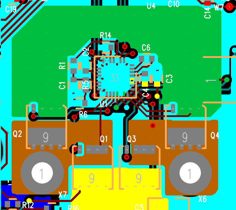
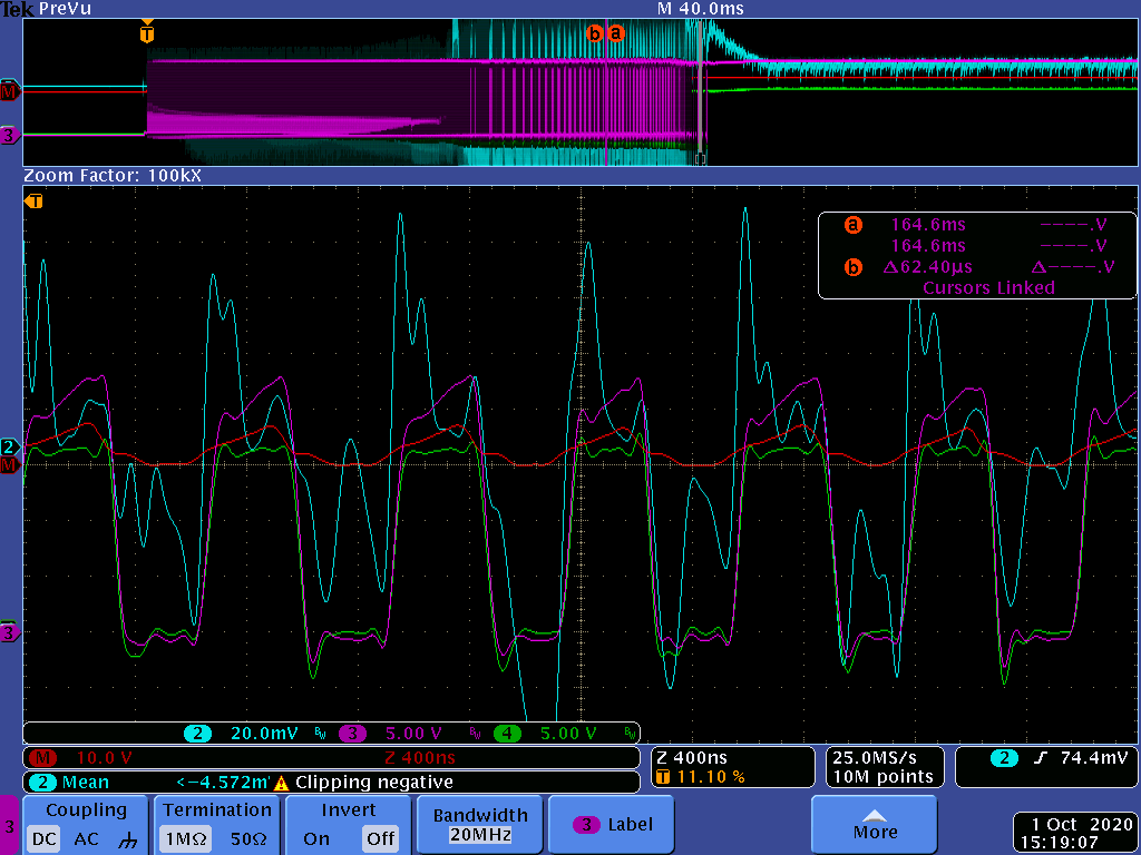
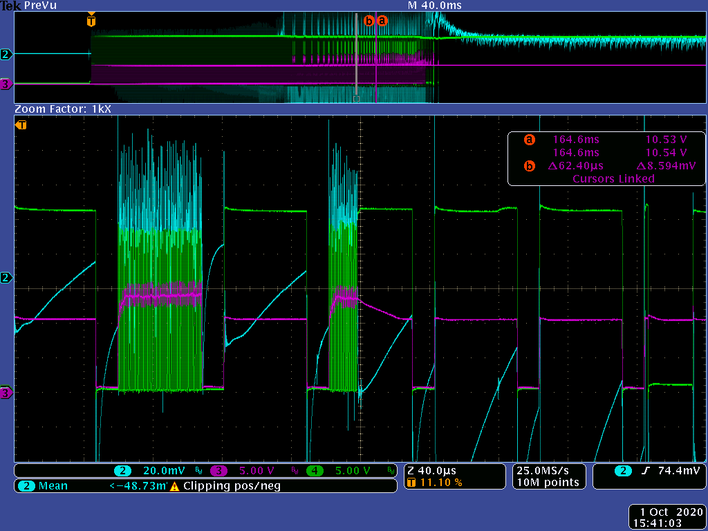
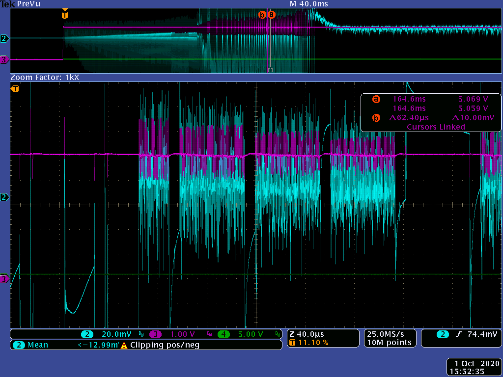
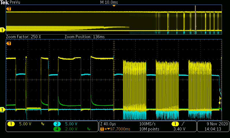
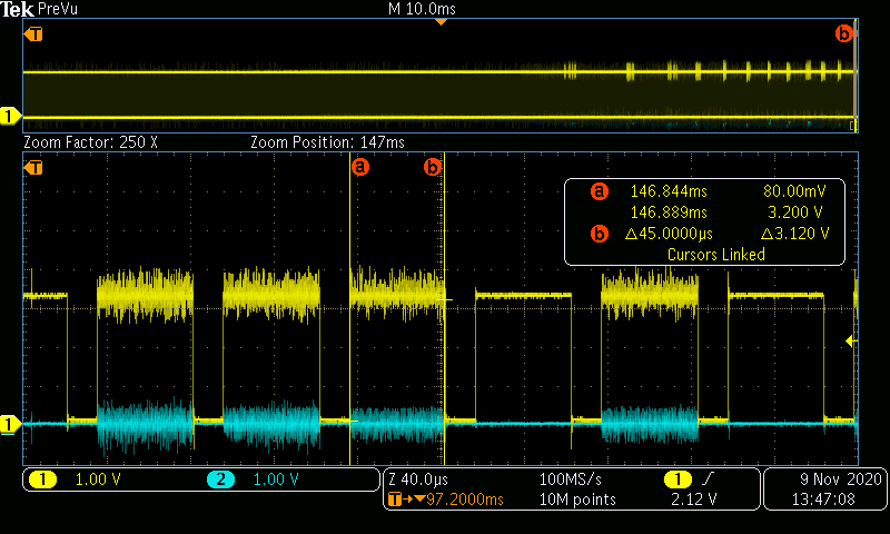
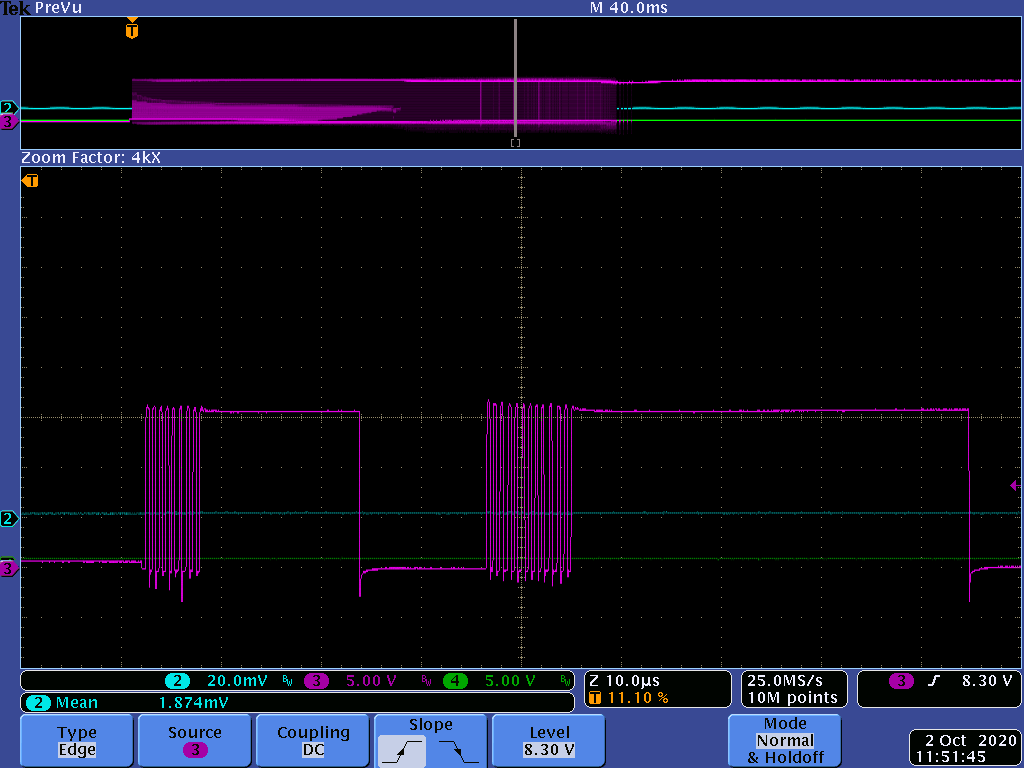
Hopefully the schematic and layout portions of the DRV8702 pasted okay above.  I'm having an issue with the DRV8702 in that the high side gate driver starts to pulse VERY fast.  The attached screenshot of the source pin of Q1 shows that it is being turned on and off at a 50% duty cycle with a period of 300nS.  That doesn't match up any fault conditions that I can find in the datasheet, so I believe the DRV8702 is malfunctioning.  I'm not able to check the nFAULT pin, as it is not used in this design.  I've replaced the part, and played with decoupling capacitors and grounding but am unable to get the part to consistently drive the FETs.  When Q1 is being driven this way, Q3 remains on.  If this high frequency glitch occurs for too long, Q1 fails short (this was how I found this phenomena).

Do you have any recommendations on what to look for  to try to fix this issue?  The application is a drill motor driver.  These gate pulse issue only occur during the soft start portion of the motor while we PWM the IN1 and IN2 pins.  You can see in the above scope shot that once the DRV8702 reached 100% duty cycle that things behave normally.  The gate pulses do not happen all the time, but when they do it is always on the rising edge of the source pin.

Let me know if you've ever seen this before and what you recommend to do to try and fix this!

  • Hi Robert,

    The scope image came through fine, however the schematic and layout images did not - can you try posting them again?  This might help: https://e2e.ti.com/support/site-support/f/1024/t/761613

    Regards,
    Mike

  • I've reattached them with the "insert file" button.  Before I just "pasted" them.

  • I've reattached them with the "insert file" button.  Before I just "pasted" them.

  • Perfect, your images came through.  I wish ctrl-v worked - it is much more convenient!

    I will review and come back tomorrow.

    Regards,
    Mike

  • Hi Robert,

    It looks like the MODE pin in the design is floating - is that connected to a net somewhere else in the schematic?  I am checking if this could be problematic or not.  Based on the internal PU and PD on this pin, the voltage level is in the undefined logic region.

    The rapid pulsing could be due to current chopping.  The 300ns time fits in the realm of possiblity for the FET gate rise time.  It looks like you brought out the SO signal - could you post a scope trace of the SO signal while this behavior is occurring?  Since we cannot monitor nFAULT, this is another method we can use to see if we are hitting OCP.

    Regards,
    Mike

  • Michael Erdahl said:

    It looks like the MODE pin in the design is floating - is that connected to a net somewhere else in the schematic?  I am checking if this could be problematic or not.  Based on the internal PU and PD on this pin, the voltage level is in the undefined logic region.

    From page 23 of the datasheet, it says you can leave the MODE pin floating (Hi-Z) to enable PWM mode.  As far as I can tell, the part is in PWM mode.  During the screenshot I am PWMing the IN1 and IN2 pins to soft start the motor.  The frequency of the PWM is a tad less than 20KHz, and that lines up with the duty cycle of the purple waveform above. 

    Michael Erdahl said:

    The rapid pulsing could be due to current chopping.  The 300ns time fits in the realm of possibility for the FET gate rise time.  It looks like you brought out the SO signal - could you post a scope trace of the SO signal while this behavior is occurring?  Since we cannot monitor nFAULT, this is another method we can use to see if we are hitting OCP.

    I know that the part is not hitting OCP as the other FET remains on during the pulsing.  Also, after OCP is hit the part is supposed to turn off the FETs for T(retry).  T(retry) is 3mS, and that is WAY longer than what it is doing.  It also cannot be entering current regulation, as the PWM off time for the DRV8702 is 25uS.  Nothing in the datasheet lines up for timing other than the 240nS output dead time.  But even then, I'm not sure why it would be turning the FETs on and off that quickly unless there's some other feature that I'm missing in the datahsheet.  I was able to capture the voltage on the current sense resistor and see the chip enter current regulation, but it's later on.  If you squint and study the purple waveform in the "PreVu" window of the above screenshot, you can see slower pulses right before the purple waveform stays high.  This was where the current regulation was coming into play.  It takes close to 40A or so to get the motor moving under load, then it drops to around 10A.  To add even more information, the FETs are cold as a cucumber during this startup.  The whole motor driving scenario only lasts a few seconds.  It's only during this soft start stage that I see the strange MHz gate driving that sometimes kills Q1.

    For what it's worth, it appears as though keeping the motor wires twisted and/or shielded minimizes the issue.  There's about 8 inches of wire between our board and the actual motor.  I'd say the issue is fixed, but I'm nervous that I'll see it creep up again since the board has already come back to us a few times with Q1 failing.  It sure seems to me that the DRV8702 is going bonkers for a brief period of time, potentially due to the high flux of the motor wires nearby.  Adding the shielding seems like a band-aid, so I'd like to understand what is causing this behavior before entering production.

    I can work on scoping the SO signal in the meantime.  That pin goes into our MCU so we can monitor the current.

    I have scoped the gate of Q1 during this pulsing.  See below!  The red math waveform would give you Vgs of Q1.  The blue waveform is a coax cable (1Mohm terminated) on the 0.002 ohm sense resistor, but I wouldn't rely on that too heavily as being accurate! :)

  • Hi Robert,

    Thank you for the additional information.  Talking with other folks on the team, you're right, OCP is not occurring in this short timeframe.  Very interesting observation the issue goes away when the motor leads are twisted.

    Can you also monitor the two PWM inputs and the gate of the offending MOSFET (Q1) and gate of Q3 to see what command is given to the device and what comes out on the gate signals.

    I assume VCC and VM are stable during this period?

    Also, minor thing, the signal name for the SLEEP pin is nSLEEP (active low) - just wanted to mention that out so there is no confusion later about the active state.

    Regards,
    Mike

  • Robert,

    Few additional queries from the design team:

    1. Can we get the input PWM waveform?  Suspect this might be happening due to GND bounce.
    2. The image where VGS is plotted - Is the  purple line the gate of Q1?
    3. Based on description, the expected current direction is going into source of Q1 - however looking at waveform it doesn't look like that - Can get more images like (a) Clear picture of showing unzoomed parts in above plots (b) A image with PWM, VGS of Q1 and Q2

    Regards,
    Mike

  • Mike,

    Sorry for the delay!  The board I used to capture the waveforms is currently with our customer for testing.  I should have a new unit to test soon and then I can get your requested waveforms!  To answer your other question, yes, the purple line is the gate of Q1.  The green is the source of Q1, and the red is the math between the two.  There could be quite a bit of pickup on the probes, as I had a long ground probe.

    In the mean time, I do have a couple other scope shots isn't exactly what you are asking for, but might help!

    This was a scope shot where green is Q1 gate, purple is Q3 gate.  The thing that was odd to me was that during the high frequency pulsing on the gate of Q1, Q3's gate was on the whole time.  But...after Q1 stopped pulsing there was MORE voltage on the gate of Q1.  Then it slowly dropped down to the nominal 10V.  In this same screen shot you can see the PWM action of Q1 and Q3 (although the pwm input signals are missing, you can see it is about 75% duty cycle or so around 19KHz).

    You asked if Vcc and Vm were stable during this period.  Vm is certainly stable, but the Avcc voltage looked a little odd to me.  Below is a screen shot of Avcc during the funny business.  It appears stable, but during the high frequency pulsing it looks like it is almost decaying.  Then when the high frequency pulsing stops, it recovers.  Almost as if the internal regulator of the part is being disabled.  Purple is Avcc.

  • Thank you for the update Robert!  I will share the scope traces with the team and let you know their feedback.

  • Robert,

    Few things while waiting for the team to digest the scope traces and observations:

    1) Do you have a DRV8702-Q1 EVM available for testing?

    2) The Avdd behavior is interesting, and worth poking at a bit.  I am confirming GND pins 9 and 13 are internally tied together.  The loop area from C2 back to pin 13 could be a concern.

    3) One idea to test is driving Avdd with a bench supply, and see if the same behavior exists.  If you try this, be sure to power the external Avdd supply after the device is powered to avoid back-driving.

    Regards,
    Mike

  • Hi Robert,

    Hope all is well - were you able to get another board for testing?  If you think it will still be a little while, we can close this thread, and re-open when you're ready.

    Regards,
    Mike

  • Hi Robert,

    I am going to mark this as we think resolved, but you can re-open once you have a chance to reply.

    Regards,
    Mike

  • Michael Erdahl said:

    Hi Robert,

    I am going to mark this as we think resolved, but you can re-open once you have a chance to reply.

    Regards,
    Mike

    Sorry for the late reply!  I'm just getting the second engineering unit up and running to do more tests.  It'll probably be a few more days before I will start probing things as the whole mechanical system needs to be built up before I can stress the system in the same way as the screenshots above.  I can reopen and reply to this when I have more data if that makes sense!

    -Robert

  • Thanks for the update Robert, no worries, we will be here :)

  • Hello Michael,

    I now have a complete system in engineering to test and debug.  We are certainly still seeing the Q1 (high side) MOSFET failure.  The same board I have in engineering has seen two consecutive failures.  I took a bunch of screenshots that may help shed more light on what is going on.  The gate drive on Q1 is still going crazy and we have been able to reproduce it by playing with how the motor wires.  The odd thing is that the unit failed twice after we had the motor wires in an aluminum shield and wraped with heat shrink.  Either way, you can get the controller to malfunction by playing with how the motor wires are routed.  Our MCU seems to be unaffected and continues to PWM the inputs correctly.  It still seems as though the high side gate drive starts going crazy and pulsing the FET at MHz until death occurs.  You can see the high frequency behavior in the following screenshots.  The MOSFET did not fail under these circumstances, but I believe that eventually it will if the behavior occurs long enough and violates the SOA of the MOSFET.

    In the above:

    Yellow: Gate of Q1

    Blue: Gate of Q3

    Green: SO of DRV8702

    This was with the motor wires twisted together, and no high frequency occurs.

    This is the same scope capture as above, but with the motor wires untwisted.  You can see Q1 going crazy.  It's hard to tell, but I believe Q3 was at ground during the craziness (there's just a lot of noise due to the high current at MHz switching frequency.  I had someone else doing the test in engineering, so I could repeat the measurement if there is something you would like to see in more detail.

    These are the PWM signals (IN1 and IN2).  The trace colors weren't labeled, but it makes sense that one of them is always at ground since I am moving the motor in one direction during this portion of the test.  It's interesting to note that the high frequency PWM of Q1 continues until the input signal goes back low.  It seems as though once the high frequency PWM starts to occur, it tends to stay happening (at least until the current drops?)  I'd say we could lower the current limit of the controller to help, but I'm not sure how much it would help.  Do you think it has anything to do with how during PWM we are allowing the motor current to freewheel?  The current would recover into the battery and go backwards through the sense resistor.

    Let me know of your thoughts and if there is something else you would like to see!  I have not tried the backfeeding AVcc test yet.

  • Hi Robert,

    Thank you for the additional scope traces.

    It would probably be helpful on our end to attempt reproducing the same issue - can you share the motor specs so we might acquire a similar unit for testing?

    Regards,
    Mike

  • Michael Erdahl said:

    Hi Robert,

    Thank you for the additional scope traces.

    It would probably be helpful on our end to attempt reproducing the same issue - can you share the motor specs so we might acquire a similar unit for testing?

    Regards,
    Mike

    Sure!  Here are the motor specs:

    • 12 VDC Nominal Operation
    • RS550 Typed Brushed Motor Driven at 14.8 VDC
    • Operating Current – 25A
    • Max Current – 68 A
    • Max No Load RPM – 25,928 RPM
    • Max Load RPM – 22,000 RPM

    You'd probably see similar currents if you could get a RS550 12V motor and give it a pretty good mechanical load.  When I start the motor in the system, it will hit current limit at about 45A for a few miliseconds before it drops to around 17A for another second or two.  See motor current scope shot below across the 0.002 ohm sense resistor.  I have not seen the high frequency pulses once the DRV8702 reaches full duty cycle and the motor is moving.  It only appears on startup when the current is highest.

  • Robert,

    Thank you for the motor specs!

    Regards,
    Mike

  • Just checking in to see if you have any updates on this issue?

    As additional information, if I completely disable our "soft start" (The PWM that we do to soft start the motor), the issue seems to go away.  I even spread the motor wires apart and didn't see any odd behavior.  The high frequency misbehaving of the DRV8702 seems to be related to when the INx pins go high from a low state.  Maybe more often when the motor current is high?

    I also as an experiment changed how the INx signals are driven during our soft start stage.  Instead of letting the motor freewheel during the OFF time (both INx signals low), I changed them to short the motor (both INx signals high) during the OFF time similar to how your device limits current during the chopping stage.  It seemed to have the same high frequency misbehavior.

  • Hi Robert,

    Thank you for the additional information.  I found a good RS550 motor, but have not been able to mechanically fixture it yet to load it for comparable current spikes during start-up.

    One thing we have discussed here is the loop area on the AVDD cap (your C1).  Ideally this would have a short path to pin 13 as shown in the datasheet layout example (figure 60).  Could you try shortening C1's path to ground on your current board, and see if that improves the behavior during soft-start?

    Regards,
    Mike

  • Thanks for the update!

    Michael Erdahl said:

    One thing we have discussed here is the loop area on the AVDD cap (your C1).  Ideally this would have a short path to pin 13 as shown in the datasheet layout example (figure 60).  Could you try shortening C1's path to ground on your current board, and see if that improves the behavior during soft-start?

    I have tried lifting C1, placing kapton tape underneath it, and running a direct wire up to C2's ground.  I thought it helped at first and make that one of my early solutions.  I tried sending that board to the customer and it soon failed again afterwards.  We will certainly fix that with our next board spin, but I don't believe that alone will fix the issue.  It might help reduce the problem, but it still appears and can cause a failure on Q1.

    -Robert

  • Robert,

    OK, thanks for trying that test.

    Since there are two vias between the gate drive pin, and the Q1 gate, would it be possible to cut the trace and tack in a small value resistor (10 ohm or less) and see if we can rule out gate ringing?  I've read a few app notes that talk about gate ringing setting up a positive feedback loop and causing the MOSFET to switch fast as we're seeing here.

    If you have time for another test, can you remove R1, and used an external supply to test different voltages on IDRIVE?  Table 10 in the datasheet lists several voltages and the corresponding IDRIVE setting?

    Regards,
    Mike