This thread has been locked.

If you have a related question, please click the "Ask a related question" button in the top right corner. The newly created question will be automatically linked to this question.

DRV8908-Q1EVM: SPI Messaging Details

Part Number: DRV8908-Q1EVM

Hello,

I've set up experimental hardware with the DRV8908 EVM and a PIC processor (18F2580).  The PIC SPI port is provided by a production board where the SPI port is brought out to a stick header.

I'm trying to send and receive messages from the 8908 while monitoring the signals with a logic analyzer.

I can see my messages appearing, as programmed, going to the 8908 but the returned bytes do not seem to make sense.

I've tried monitoring the SPI output on the EVM using the TI-supplied Demo GUI.  These messages too do not appear to make sense to me.

Unfortunately, the demo software constantly monitors the EVM board, so I am not able to find the message(s) that I create via the GUI in the message stream.

Could TI please confirm or correct me with regards to the following:

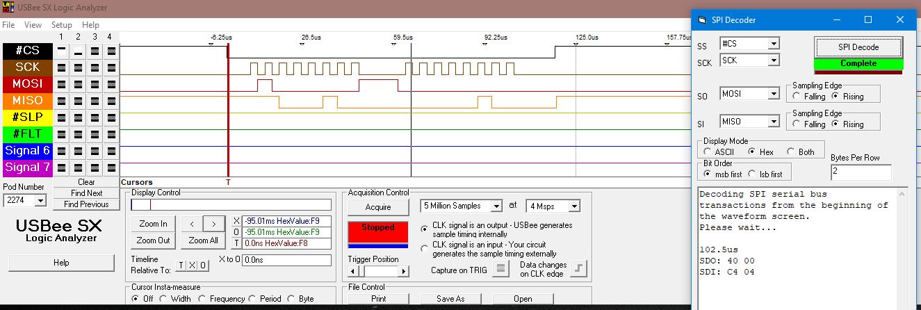
1) To read the status register, I'm sending the byte pair 0x40, 0x00.  My understanding of the return SPI stream is that the status register of the IC is the first byte and the requested information, the second byte is the register being written to.  The response that I'm seeing on the logic analyzer varies but I'm getting the following byte pairs back in response:  0xC4, 0X04; 0xC6, 0x04; 0xC0, 0x04..    If I'm following the information in the data sheet, these two bytes should be the same value for a 0x40, 0x00, command.  Are these responses I'm seeing sensical?  If so, could you please help me understand the breakdown of the response byte messages?

2) I've also tried to send a multiple DRV part message by constructing the HDR1 | HDR2  | ADR | DAT message format.  Per the data sheet it appears that the !CS input is held low for the entire multi-part message transmission.  My code maintains !CS as low while sending the stream of bytes.  Confusingly, in the data sheet there is a discussion that seems to indicate that I need to de-assert the !CS signal every two bytes.  That's not what is being shown in the illustration for the multiple part messaging.  The messaging I see with the EVM using the Demo GUI seems to indicate that I need to cycle the !CS every two bytes as well.

A) Does the !CS signal stay low for the entire duration of a multiple message?

B) If sending a single two-byte message, I assert then de-assert the !CS signal, correct?

B) Can I send a multiple message to a single part with the number of devices being '1'?

Thank you in advance for your time,

  • Hi Chip,

    Can you attach some images of your logic analyzer output?  The status codes are indicating an UVLO condition - if VDD comes up before VM this could be why you're seeing this bit set.  It will remain latched until writing a '1' to the CLR_FLT bit in the CONFIG_CTRL register (address 0x7).  Can you try setting CLR_FLT and report if UVLO is cleared?

    To answer your questions:

    A) Does the !CS signal stay low for the entire duration of a multiple message?

    Correct.

    B) If sending a single two-byte message, I assert then de-assert the !CS signal, correct?

    Correct.

    B) Can I send a multiple message to a single part with the number of devices being '1'?

    Yes, this should work.

    Regards,
    Mike

  • Mike,

    Images below / attached.

    I was not aware that there was a power sequence requirement for VM / VDD.  Could you please direct me to the information on the data sheet?  Right now VDD and VM are tied together to keep things simple (5.2V).

    Based on the second byte, I agree, UVLO is set.  Which I found odd.   Does having this bit set mean that the SPI output from the 8908 will be inaccurate or that the part will behave in unexpected ways?  Or, is it just an indication of an event?

    What can you tell me about the first byte being 0xC4, etc?  Isn't that byte supposed to be a copy of the status register of the IC? 

  • Mike,

    Coming back to this topic.

    Updates on my end:

    Found out that the SPI configurations on my micro were not compatible with the DRV part.  I am now able to read and write to the registers and the messages I'm seeing on the logic analyzer square with the messages my micro are receiving!

    There is still confusion about the first byte and what it actually means.  If I read the status register as my message, the register value that is returned is not the same as the value of the first byte. 

    Any insight on this first byte?  I'd like to know how to interpret the byte.

  • Hi Chip,

    It looks like my previous reply did not post - sorry to leave you hanging!

    The first return status byte will always have to two MSB's asserted, so what you are seeing is normal.  Does that clear things up for you?

    Regards,
    Mike

  • Mike,

    Thank you for explaining that.  This explains it all.

    Chip