This thread has been locked.

If you have a related question, please click the "Ask a related question" button in the top right corner. The newly created question will be automatically linked to this question.

DRV8353R: About DRV8353 Gate Drive

Part Number: DRV8353R
Other Parts Discussed in Thread: DRV8332, DRV8312, DRV8353

Hi 

In our boards evaluation, following phenomenon is occurred.

I would like to ask about gate drive of DRV8353HR.

(Phenomenon)

 - If I use PWM frequency 200kHz,  less than duty 5%(lass than high time 250ns) , this driver's gate control was not operated. 

 -Even if a fixed Duty PWM signal is input to INHx. Gate Drive on duty seems to slightly change automatically.

(  It is using 3×PWM mode. Since we are doing first evaluation, I am useing with INHA:High, INHB & INHC:Low. I haven't controlled the motor yet.)

(Question)

 - Are there any requirement of minimum on duty cycle of PWM?

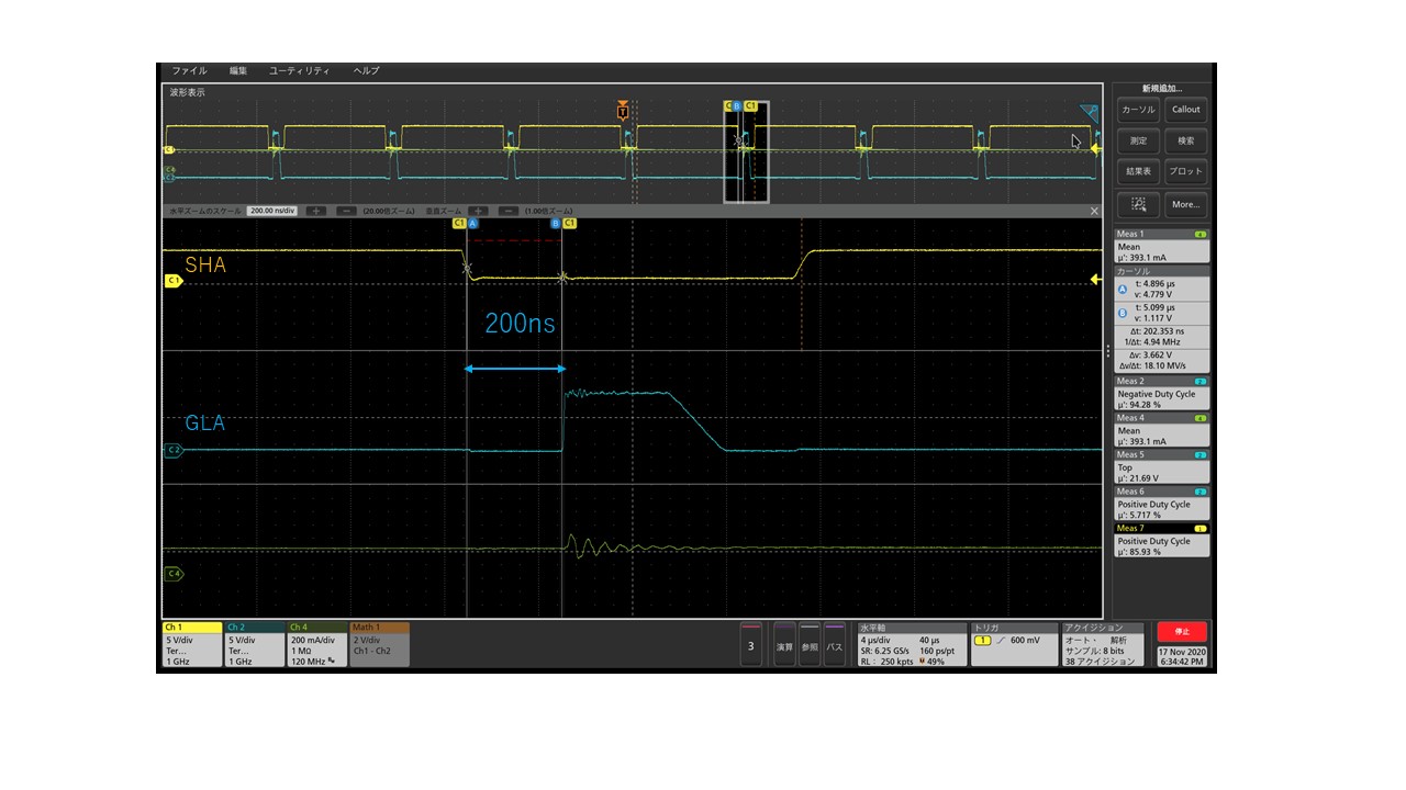
 -  I checked GLA and SHA signal, it seems deadtime is 200ns,(Attached file )

    According to the datasheet, gate drive dead time is 100ns(HW device).

    Is this time changed automatically?

 -  Even if a fixed Duty PWM signal is input to INHx(3×PWM mode). Is gate frive on duty cycle slightly change automatically?

     In short, isn't  the current value fixed even with a fixed-duty PWM signal input?

Best regards

Naoki

  • Hello Naoki,

    Thanks for posting on the motor driver forums. Let me confer with the team and see if I can give an appropriate answer by 11/20/20.

    Note, it doesn't look like your attachment was not uploaded correctly, can you please try again?

    Best,

    -Cole

  • Hi 

    Ok, I look forward to hearing from you.

    I attached Oscilloscope waveform.

    It is This is SHA and  GLA waveform, The condition is input to INHA at a frequency of 200kHz.

    Best regards

    Naoki

  • Hello Naoki,

    I see you're checking out commutation for some different devices. Is there a specific specification you're trying to meet with the duty cycle accuracy questions? Maybe I can help offer some other insight.

    Onto your questions.

    Are there any requirement of minimum on duty cycle of PWM?

    If you have a high time of 250ns, this easily starts to interfere with timing associated with TDRIVE architecture so I'm not surprised that the output duty cycle doesn't change with smaller on times.

    I suggest reading the Smart Gate Drive architecture app note (specifically the TDRIVE implementation section specifically) in combination with the datasheet to understand the timing. You can find the app note here: https://www.ti.com/lit/an/slva714c/slva714c.pdf 

    Gate drive dead time is 100ns(HW device). Is this time changed automatically?

    Small reminder that the dead time value given in the datasheet is the typical value. The real dead time will have some variance. Normally, this would be contained in the min and max specification but its clear that the device was not designed nor tested to specific guardband for the min and max values.

    Not to say that the dead time is uncontrolled, but you should expect a +2.5 times the amount in the datasheet as a maximum (where the minimum is probably closer to 75% of the typical value). These are rules of thumb based on design rules so they cannot be held to the same standard as a number that belongs in the datasheet. Looks like this device specifically falls closer to the maximum expected from the design rules.

    Even if a fixed Duty PWM signal is input to INHx(3×PWM mode). Is gate drive on duty cycle slightly change automatically? In short, isn't  the current value fixed even with a fixed-duty PWM signal input?

    I'm not sure if I totally understand the question, and I apologize for that. Let me know if the app note on the smart gate drive architecture helps answer the question. 

    Best,

    -Cole

  • Hi 

    Thank you for answering my questions.

    I would like to ask other questions.

      -Does the minimum ON Duty requirement time change depending on the IDRIVE value?

      -Can you tell me about minimum duration time requirement of input PWM?

       (The condition that there is no time for rise time and fall time of gate.) 

    Best regards

    Nishimura

  • Hello Nishimura,

    I will give a more complete answer tomorrow, 11/24/20, if that is alright. We have a holiday here in the US which has been causing delays in responding on E2E. I ask for your patience, as a result.

    Thanks,

    -Cole

  • Hello Nishimura,

    Does the minimum ON Duty requirement time change depending on the IDRIVE value?

    Yes, IDRIVE affect rise and fall time. A typical rise and fall time is about 100ns, so  2*100ns/5000ns * 100% = 4%, assuming period is 1/200kHz = T allowed which means you've already lost 4% to the minimum input PWM. If this feels too slow, you could always try and make IDRIVE higher (which could lead to other things, like damage) which should decrease rise and fall time. However, we're just talking about typical use case and how IDRIVE could affect the rise and fall time, and therefore, the minimum PWM input.

    Can you tell me about minimum duration time requirement of input PWM?

    There really isn't one. As soon as the VIH is crossed and TDRIVE architecture is in a state where it can accept a transition, it'll go through the motions of turning the gate on or off. By the end of the TDRIVE transition, it'll check the state again and react accordingly. As such, the input can be as small as you'd like but the output is only going to react by the TDRIVE architecture (as mentioned previously).

    Best,

    -Cole

  • Hi 

    Thank you for answering our questions.

    I want to ask other questions.

    Attached file is waveform movie of INHA(Yellow), SHA(Blue).

    (Green waveform is current waveform. Because IDRIVE is setting 1A/2A, so ringing is occuring)

    Even If MCU is putting fixed on duty cycle into INHA, SHA's on duty cycle is automatically change like attached movie.

    It seems that it is changing approximately ±50ns.

    If input PWM is 200kHz,  the control current value is always varies when the On duty is low.

    It is serious problem for us  when  doing current control.

    Why is this behavior happening?

    According to the datasheet Propagation delay(tPD) time is 200ns. 

    Does this time always change?

    Best regards

    Naoki

  • Hello Naoki,

    I'll try to give you a good answer next week after this holiday.

    Best,

    -Cole

  • Hello Naoki, 

    I understand, yes, the dead time seems to be changing automatically. I've learned that the dead time does not have a minimum or maximum specification and has not been designed nor tested to be tightly controlled. I'm sure if you measured those time individually, they should give you a puesdo-min and max specification.

    I realize this makes your job difficult because we can't accurately derive a maximum duty cycle if the dead time cannot be accurately determined. As such, the typical use case can still be derived with the typical values and you need to account for some error in the real waveform based on your measurements. I will warn you that this is difficult as we expect changes over process and temperature which will, again, prevent you from accurately determining the duty cycle you can guarantee outside of the typical use case.

    Let me know your thoughts.  

    Best,

    -Cole

  • Hi 

    I understood that this phenomenon is caused by dead time.

    I asked the following E2E question before, is it correct that DRV8312 or DRV8332 is suitable for our requirement? Because this device has not controlled deadtime automatically.

    https://e2e.ti.com/support/motor-drivers/f/38/t/958234

    Best regards

    Naoki

  • Hello Naoki,

    The DRV8312 or DRV8332 still has a dead time spec, its just around 5nS which is much less than the 100s of nanoseconds you're seating with the DRV8353. It is a typical spec so we do expect it to have variance as well. In fact, all gate drivers I've ever seen (including the competition) will incorporate dead time automatically as the user is not trusted with transitioning correctly (which will prevent shoot through and blowing up the FETs). 

    I also want to be as clear as I can when I say that I don't understand your specification. You have only asked questions about equivalent duty at the maximum frequency that a DRV can support. The PWM frequency doesn't seem to be a consistent, just "as fast as the device support" which leads me to believe you might be okay with changing the PWM frequency to something slower if it gave you better control over the duty cycle percentage. 

    Further minimum duty cycle isn't a specification I've seen, only minimum mechanical speed. This means, calculated losses within the power stage, the motor parameters variance over temperature and manufacturability, and others all play a role (in addition to the timing variance, which is what you've posted about). So, if you have a specification in mind that translates to actual motor performance, I might be able to help you more comprehensively. Otherwise, if understanding the minimum PWM duty cycle and its variance is all you need, I suggest you check the DRV8312 on the bench for its variance as well.

    Best,

    -Cole