This thread has been locked.

If you have a related question, please click the "Ask a related question" button in the top right corner. The newly created question will be automatically linked to this question.

DRV8889-Q1: Overheating very quickly - abnormal temperature behaviour

Part Number: DRV8889-Q1

Background

I have the DRV8889 soldered to a PCB and connected to an ATmega4809 mcu. 

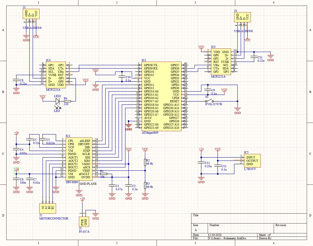
The circuit is a copy of the "recommended circuit" from the datasheet. Motor is running @24 V.

Here is my schematic of the connections between the driver and my mcu.

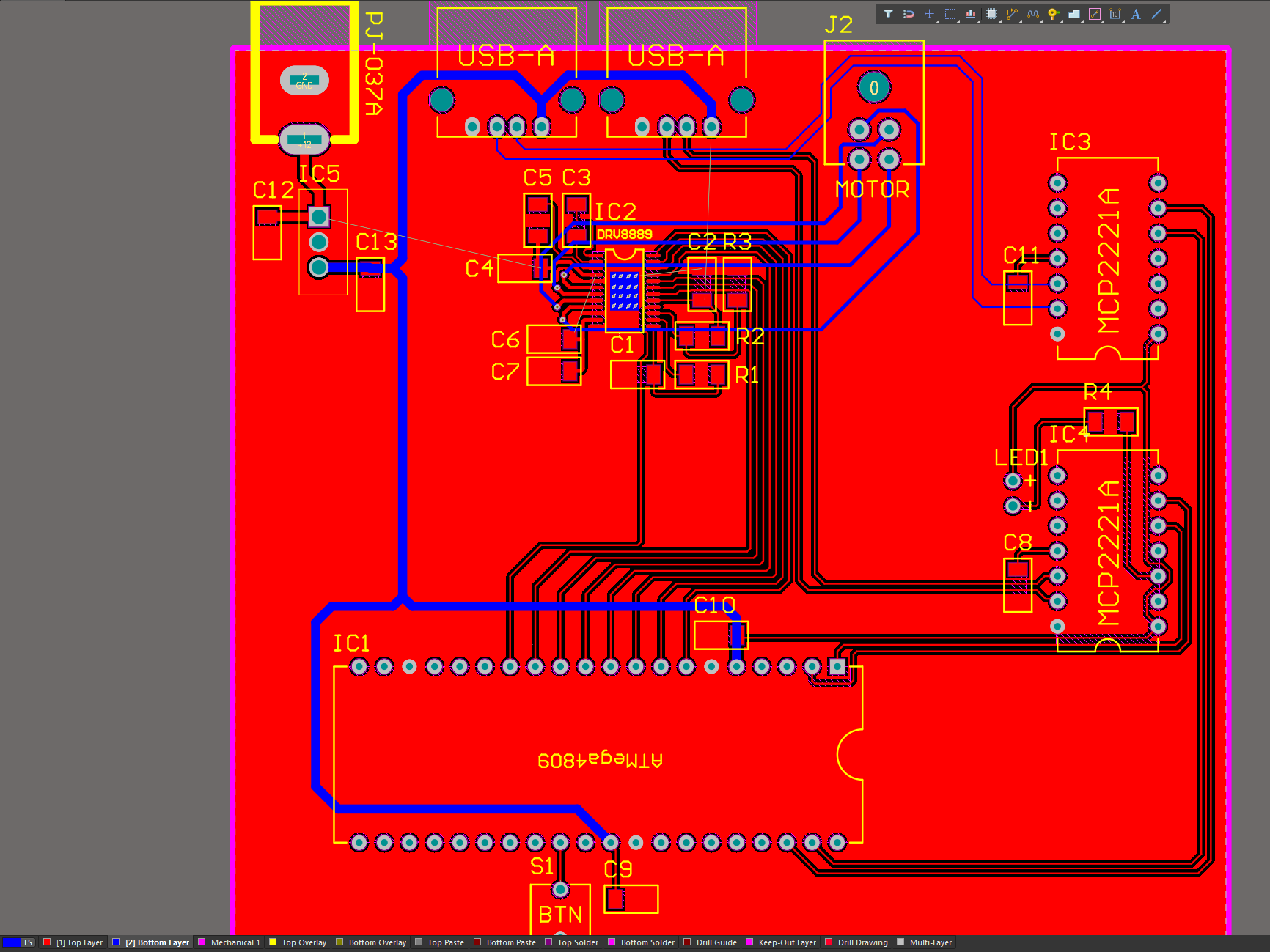
Due to a Git error, I have lost the most recent version of my PCB. This version is very similar with the exception of some traces still unrouted. I'll still include a screenshot in case someone finds it usefull.

Link to my motor: www.digikey.ca/.../11564434

The motor does not overheat.

Behavior

Ctrl register one = 00110000 (Trq = 81.25%, everything else default)

Ctrl register two = 00001111 (DIS_OUT = 0, everything else default)

All other registers are normal.

Motor turns on and works as expected. After about 10 seconds of operation, the overtemp warning is triggered. After about 15 seconds the overtemp fault is triggered. At this point, the DRV is extremely hot to the touch (to the point where it is painful to touch). 

I have attached a small copper heatsink to the chip which helps a bit, but it eventually overheats the same way.

When it is not overheating, it works find.


Soldering

I soldered this by hand with an iron. It seems to have worked fine but I'm wondering if I somehow damaged it by heating it for too long?

Thanks in advanced for any help or suggestions. 

Best Regards,

Brian

  • My images didn't upload properly. So here is the schematic:

    Again, this is the incomplete PCB. I accidentally deleted the most recent version with a git error. A few traces are not routed yet such as some of the 24v inputs. 

  • Brian,

    How did you solder the exposed pad at the bottom of the IC to the PCB?  Did you use some solderpaste on the PCB and use hot air to ensure a good connection between the exposed pad and the exposed copper area on the PCB?  

    I suspect that might be your problem.

  • Hi Brian,

    Thanks for updating your pictures.  One simple thing might be a bad connection to the thermal pad - is that soldered?  I only ask because you mentioned hand soldering.

    By default the stepper driver will be in full-step 100% current mode.  You can try changing the microstep mode in CTRL3.  If you need full-stepping mode, drop down to the full-step at 71% current.

    Also check out the stall detection section in the datasheet.  You can take a look at the TRQ_COUNT register to see if you're getting close to stalling.  If you're in not danger of stalling, your can also drop the TRQ_DAC value to match what is needed.

    Finally, if you have any doubts about damaging the driver, check out section 8.2.4.1 Power Dissipation in the datasheet.  Plug your values into the thermal equations, and get an idea of how hot the device should be getting when driving the motor.  If this checks out, then the device could be damaged, or some other board issue.

    Regards,
    Mike

  • Hi! Yes I forgot to mention how I did that. I added an exposed copper pad with vias on the bottom of the 2 layer board (see pcb). I first melted some solder on the top side copper. Then I placed the IC on the hardened solder and heated it up from the bottom while adding a bit more solder from the bottom (it flowed through the VIAs). It seemed to have a good connection - before I soldered the pins it was already fixed to the board.

  • Hi! Yes I forgot to mention how I did that. I added an exposed copper pad with vias on the bottom of the 2 layer board (see pcb). I first melted some solder on the top side copper. Then I placed the IC on the hardened solder and heated it up from the bottom while adding a bit more solder from the bottom (it flowed through the VIAs). It seemed to have a good connection - before I soldered the pins it was already fixed to the board. In addition to the ground plane, I also have two copper heatsinks - one on the top and one on the bottom.

    As explained in my original post, I am using TRQ = 81.5%. I also have my VREF at 2.5V. When I run it lower, I don't have enough torque. Ideally, I would like to run it at a higher current (as close to 100% as possible). 

    I will take a look at the power dissipation in the datasheet, but I have a feeling this is not normal... Why would running this chip at it's spec voltage - with a ground plane and heat sink be overheating?

  • Hi Brian,

    I went through the thermal calculations listed in the datasheet out of curiosity, and noticed the default slew rate of 10V/us is going to strongly heat the device at your full-scale current setting.  Please try increasing this (CTRL1 register) and see if the behavior changes.

    The other variable that will strongly affect your device temperature is the PWM frequency.  What are you running?  If you're running less than 30KHz, I suspect slew rate may be the culprit.

    BTW, do you have access to a TI EVM for this device as a control experiment?

    Regards,
    Mike

  • I changed the slew rate to 110 V/us and it works much better. Now it takes over 3 minutes before overheating. Any other suggestions that might help me out? My PWM rate is very slow btw.

  • Sorry, forgot to answer the part about the EVM - I don't have one. 

  • Brian,

    What is "very slow"?  You may need to experiment with different decay modes if you're running the stepper very slow.

    Try "Smart Tune with Dynamic Decay" (110b in CTRL2) and "Mixed Decay for Increasing and Decreasing Current" (100b and 101b in CTRL2).

    Also test increasing the Toff period in the same register.

    Do you by chance have access to a current probe?  It would be interesting to see the current waveform on one of your phases.

    Regards,
    Mike