This thread has been locked.

If you have a related question, please click the "Ask a related question" button in the top right corner. The newly created question will be automatically linked to this question.

DRV8353: The gate driver does not work. FAULT condition all times

Part Number: DRV8353

Hello

We have integrated the DRV8353HRTAT module into one of our products under development and we are unable to get it started. We always have the fault condition present some time after the "Enable" signal is triggered.

1. What happens if we put all inputs (INLx, INHx) to 0? Will the fault signal be triggered?


2. FAULT is active by entering any mode (Digital inputs at very low speed); Synchronous PWM at 10, 15, 20 Khz (dead time of 600 ns)

3. The FAULT condition is not reset by introducing a low signal for 30us. It only resets for a moment when we come from sleep mode (1ms)

- Could you tell me how we can verify the correct operation of the module? I need to know the value of inputs that we should put.

- Should we test it with a motor connected to the power stage or should it not be necessary?

The driver configuration is as follows:

VM: 12V (not the same as DRAIN)
VDRAIN: 24V

FAULT: Pull-up to 3.3V (10K)
IDRIVE: Pull-up to DVDD (18K) -> Mode 6
VDS, GAIN: 0 ohms to DVDD (Overcurrent protection disabled - 40V / V)
VCP: 1uF to VDRAIN
VREF: 3V

The MOSFET gate characteristics on the power stage is

No gate resistor (IDRIVE control current)

Vds: 100V
Rdson: 1.5mOhm
Gate charge total: 211 nC
Worst Case Threshold: 4.3V

  • Hello Francisco,

    1. What happens if we put all inputs (INLx, INHx) to 0? Will the fault signal be triggered?

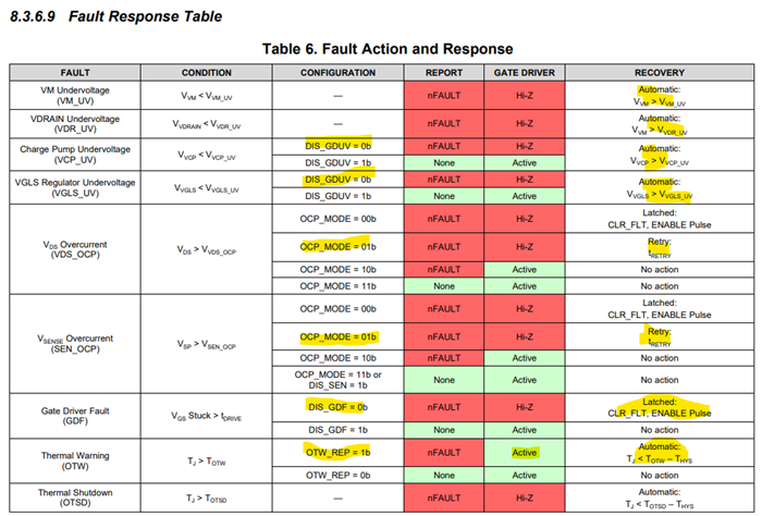
    In most cases, no fault signal will be triggered. As the table shows, when the drivers HI-Z, no gate will be turned on and current will not flow through the FETs. If current was flowing through the FETs, then the gate driver went HI-Z, and current was still flowing (through damage or otherwise), the DRV would throw a gate drive fault. Or, while turning off the FETs, BEMF from a spinning motor were to damage some rail and cause an undervoltage fault, then there would be a fault.

    In normal cases, this would be considered "idle", as the gates of the FETs weren't doing anything.

    2. FAULT is active by entering any mode (Digital inputs at very low speed); Synchronous PWM at 10, 15, 20 Khz (dead time of 600 ns). 3. The FAULT condition is not reset by introducing a low signal for 30us. It only resets for a moment when we come from sleep mode (1ms) 

    So the nFAULT is latching? There's no typical retry time in the waveform where nFAULT tries to reset without any input from you? This would indicative of damage to a rail or improper assembly causing the rails not to come up correctly after enable goes high.

    I've listed the fault table from the datasheet below highlighted the criteria for for hardware devices, I suggest you check the criteria against your system and see you can isolate the fault:

    Best,

    -Cole

  • Dear Cole,

    Thank you very much for your support, finally I found the problem!

    I checked all values in the table, all OK except Vsp (SEN_OCP).

    Solution:

    Our configuration has 2 shunt resistors (not 3 as DRV8353 has the capability). The third shunt was floating and SP+ value was ~8V with respect to ground, the threshold is 1V.

    Shortcircuit between SP+ and SP- and problem solved. 

    PD: Maybe is a good idea to update the datasheet and indicate that SPx SPn inputs shall not be left floating due to internal pull-up or something. Is hard to find the relation between OPamps and this protection (is only indicated on Figure 35)

    The topic is closed.