This thread has been locked.

If you have a related question, please click the "Ask a related question" button in the top right corner. The newly created question will be automatically linked to this question.

DRV8353R: Pwm signal is not working in GHA,GHB,GHC

Part Number: DRV8353R

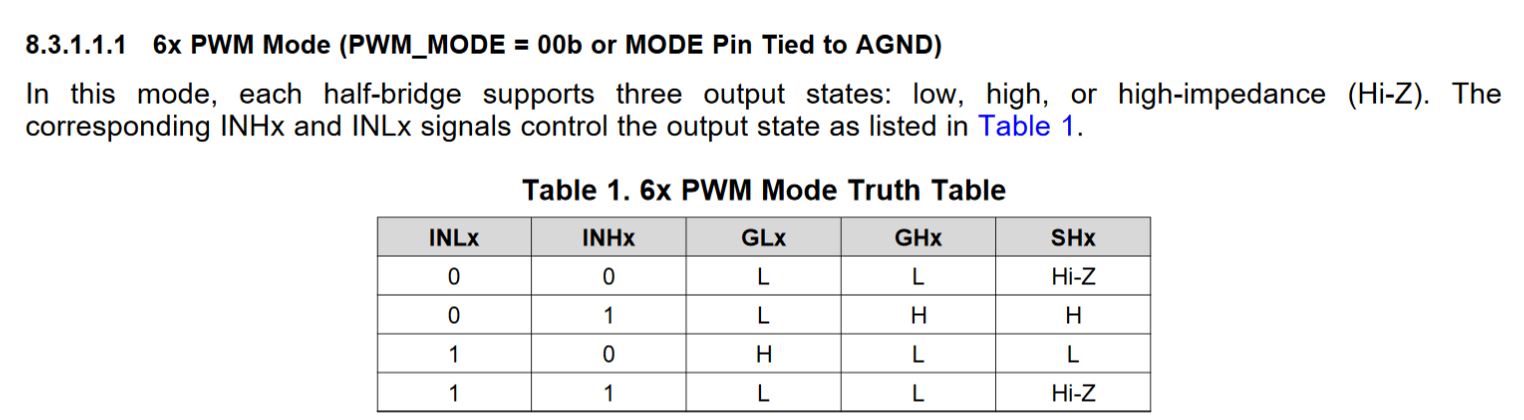
we have done the assembly as in the attached pdf. We  are not able to generate the pwm signal from the driver.

We have tested and verified that input is going to the pwm1H,pwm1l,pwm2h, pwm2l,pwm3h,pwm3l. and the pin is enable in the pin no 33..but there is no response from the driver,we are not able to generate any signals from the driver.

BLDC-SCH 21-08-20.pdf

  • Hello Gopi,

    Thanks for your question!

    Can you check the following:

    • Voltage on pin 40 (DVDD) - this will indicate if the part is awake
    • Voltage on pin 7 (VCP) - this will indicate if the charge pump is working properly
    • Voltage on pin 28 (nFAULT ) - Is the part in a fault mode?
    • Read the contents of registers 0h and 0h to check what fault condition is occurring

    We do recommend placing a small resistor (10 ohms) in series with GHx and GLx in case the external MOSFET QGD is too small compared to the 50mA minimum IDRIVE setting.

    Thanks,

    Matt

  • Hi,

    we have checked as per your suggestion and please find the below details.

    voltage on pin 40(DVD)-  4.58 v.

    voltage on pin 7(VCP)- 10.76 V

    Voltage on pin 28(n fault)- 0v

    we are not getting the output signals from  GHX pins .

  • Hello Gopi,

    You are in a fault condition (nFAULT = 0). Are you able to read the SPI registers (0h and 1h) to diagnose which fault is occurring?

    Thanks,

    Matt

  • Hello Matt,

    We are doing intial level testing for the board to drive  the pwm signal just by applying i/p signals to the INXH and INXL pins .

    we are activating the pin using enable pin 33.

  • Hello Gopi,

    Have you tried this same test on multiple boards & parts or just on one board & part?

    I assume you re not doing any SPI configuration at this point. Is that correct?

    DRV8353R will initialize with the default register settings, and some of these settings may not be ideal

    • IDRIVEP_HS maximum (1A), could cause damage to system due to too fast switching
    • IDRIVEN_HS maximum (2A), could cause damage to system due to too fast switching
    • IDRIVEP_LS maximum (1A), could cause damage to system due to too fast switching
    • IDRIVEN_LS maximum (2A), could cause damage to system due to too fast switching
    • VDS_LVL (1V), could be too high to protect the MOSFETs

    Are you applying the same pulse to INH and INL simultaneously? Or are you applying the pulses one at a time?

    Thanks,

    Matt

  • Hello Matt,

    I have tried in three different boards .

    Yes i am not using SPI configuration .

    Still now there is no damage to the MOSFETs .

    We are not getting output from GHx.

    yes we are applying the Same pulse to INH and INL simultaneously .

    still we are confused  why we are not able to get the output signals.

  • Hello Matt,

    Can you share me your Email and the contact details so that it will be very useful to discuss on this project in detail.

  • Hi Gopi,

    When you apply the same pulse to the high-side (INHx) and low-side inputs (INLx), the output will remain OFF based on the 6x PWM table:

    Thanks,

    Matt

  • Hi Gopi,

    I will send you a private message over the E2E system.

    Thanks,

    Matt