This thread has been locked.

If you have a related question, please click the "Ask a related question" button in the top right corner. The newly created question will be automatically linked to this question.

DRV10987: Power dissipation calculation

Part Number: DRV10987
Other Parts Discussed in Thread: TIDA-00281

Hi Cole and David,

Thank you very much for publishing the application report SLVA938A. It was well written.

I have a question on Equation 5 on calculating P_RDS. Could you please explain how the coefficient 1.5 come from?

Since R_DS(ON) in the equation is sum of RDS(on) for both the high-and low-side FETs, I believe R_DS(ON) per MOSFET is 1/2 of R_DS(ON) in the equation in most BLDC applications. Thus, P_RDS=3/4 *R_DS(ON) * (I_OUT_RMS)^2. Here R_DS(ON) is for each MOSFET. I am wondering whether 3/4 is the duty cycle of the MOSFET for sinusoidal control. Typically, the duty cycle of blocking commutation is 1/3 since only one phase is on each time for three-phase BLDC.

I believe I_OUT_RMS here is current per phase, which equal to I_IN/sqrt(3), where I_IN is the input current for the motor controller. Thus, P_RDS per MOSFET can be simplified as 1/4 * R_DS(ON) (per MOSFET) * (I_IN)^2. Is this correct?

Thanks and I look forward to hearing from you,

John

  • Hello John,

    Glad you liked it.

    RDS ON Calculation

    Here's the best way I can explain.

    RDSon/2

    You're correct here. In the app note, RDS(on) is defined as a the sum of low side and high side so if we take 1.5 (which wasn't my preference, 3/2 would have been better), we can take the 1/2 slide it up against the RDS(on) defined in the equation. So, excluding the "3" coefficient, we know current is "flowing through a FET" in this case.

    "3" or the simplified case

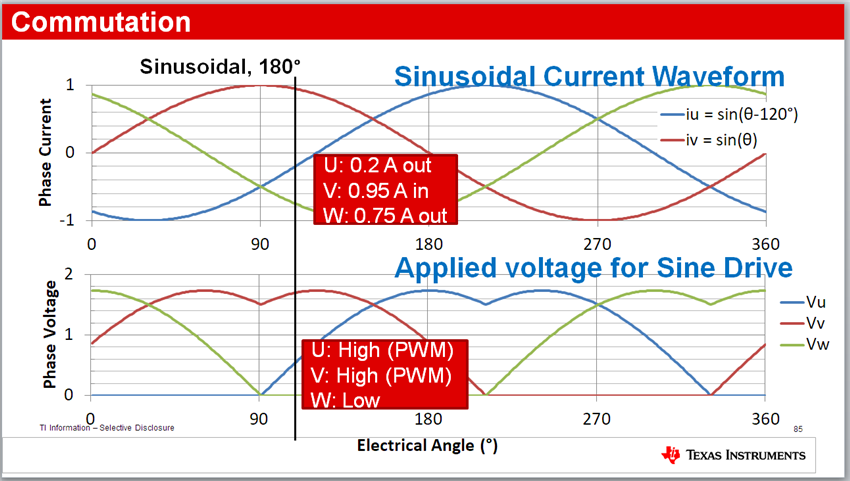
    So why 3? The simple explanation is that I need to multiply by 3, one for each phase,  for the assumption that one FET will have RMS current flowing through it at any given time over the course of a period. Below is the figure I use to explain this:

    The key to this simplified assumption is the phase voltage but first we need to talk about current. The phase current sinusoidal current 120 degrees out of phase with each other with the same amplitude (simplified further to 1A peak for this exercise). So I've drawn a vertical line to show that, for a majority of the time, there is current flowing in and out of all 3 phases and crossing the x axis will trigger the result that instantaneous current flowing through a phase is 0A.

    How do I get current to flow in and out of 3 phases at one time? I need to change the average voltage on the phase. In the case of my vertical line, the average voltage for V_V is rather high, almost 100% of the maximum applied voltage. V_U is kind of low, maybe around 25% of maximum applied voltage. V_W is 0% of the applied voltage.

    So how does this relate to what's happening to the FET? This is why the voltage in the red box says PWM for U and V, and Low of W. That means, The lowside FET is on for W (current will flow through lowside FET and RDSon of W), and high side FETs are seeing current on the high side FET RDSon of U and V. U_FET + V_FET + W_FET = 3 FETs or multiplying by 3.


    What about PWM'ing and RDS? Surely the current doesn't flow through the FET for the entire period

    In general, you'd be right. 

    Most of the DRV10x datasheets have the point that the applied voltage is really replaced with a PWM so if I low pass filtered the PWM waveform, we'd get the "third harmonic sinusoidal waveform" you see in the phase voltage picture above. So now we need to understand what's going on when we PWM on the phase.

    In general, PWM high means current will come from the supply, or VCC in the case of the DRV10x. PWM low means current comes from GND. The PWM high case, current can really only flow from supply to phase if the FET is actually turned on and current has to flow through the RDS of the FET. In the PWM low case we have two options, the body diode of the LS FET or the RDS on the LS FET.

    In the case of DRV 10x, we will turn on the low side FET, when the high side FET is not on and we are in a section where the applied voltage will be nonzero. So we can ignored diode losses that case so current is still flowing through 1 RDS on of a FET--it just happens to be shared between high side and low side. Some other algorithms don't do this but DRV10x does. Trying to follow your logic, this is why you shouldn't get the 1/4 at the end of the equation but I haven't done the analysis to understand what will happen if the body diode is used more often and I can simplify it to 1/4.

    In the case where we have dead time and don't want to turn a HS and LS FET on at the same time so both have to be on and current has to come from body diode of the low side. I argued that this dead time is so small that it doesn't contribute to a significantly the overall average over the course of a period so it can be ignored. Might not be true, theoretically, if dead time is similar to electrical frequency or the period of these waveforms, but, practically, the commutation probably won't work so its not a use case.

    Edit: Duty cycles in the equation

    You'll also notice the equation doesn't depend on the instantaneous duty cycle applied to the phase nor does it try to predict what it will be based on VCC*%_averageAppliedDutyCycle. This is because we don't want to try and predict what the current through a phase of a motor will be. This starts to depend on R, L, J, u_friction, (or load) which I won't want to take into account as PhDs continue to toil over equations and predict what this will be. I simply as the reader to measure it and be done, much easier for them and me. 

    Hope that makes sense, its a hard concept for most.

    Switching losses

    By the way, I realize I gave the switching losses equation  for 1 FET. I did not package it together to explain how this relates to 3 phases and the high side and low side over a period like I did for the RDS on. This was a miss in the document, I have not personally done that analysis, and I will not be able to provide that any time soon.

    This means, the power dissipation equation for switching losses will be significantly lower than RDS(on). My experience says switching losses will always be significantly lower than RDS(on) when trying to push higher current (faster speeds or higher loads) so it isn't a big deal. It will be a big deal when load is light and  the speed is slow.

    Just trying to be helpful as you use this app note.

    Best,

    -Cole

  • Hi Cole,

    Thank you very much for your detailed and thoughtful explanations. I would like to confirm two things:

    1. The power dissipation calculated by Equation 5 is for the total power dissipation of all six MOSFETs. The power dissipation of each MOSFET will be 1/2 * R_DS(ON) (per MOSFET) * I_OUT_RMS^2.

    2. Is I_OUT_RMS the phase current, which is I_IN/sqrt(3)? Here I_IN is the input current from the battery. If it is the phase current, the power dissipation of each MOSFET will be 1/6 *R_DS(ON) (per MOSFET) * I_IN^2. If I_OUT_RMS is the same of I_IN, the power dissipation of each MOSFET will be 1/2 * R_DS(ON) (per MOSFET) * I_IN^2.

    Thanks,

    John

  • Hello John,

    1. The power dissipation calculated by Equation 5 is for the total power dissipation of all six MOSFETs. The power dissipation of each MOSFET will be 1/2 * R_DS(ON) (per MOSFET) * I_OUT_RMS^2

    Almost correct. The power dissipation of each MOSFET will be (R_DS_ON/2) * I_OUT_RMS^2. Where R_DS_ON = sum of RDS(on) for both the high-and low-side FETs, and I_OUT_RMS = RMS output current being applied to the motor winding.This is exactly what you wrote.

    If at every instantaneous point in time throughout the period, there were 6 MOSFETs on, then you would multiply this equation by 6. But, this is impossible for sinusoidal drive (or any half bridge, because of shoot through), as there are 3 FETs on at every instantaneous point in time for a given period. So we multiply your equation you wrote by 3 to get equation 5 in the app note. As a result, equation 5 is correct and does not need to change.

    2. Is I_OUT_RMS the phase current, which is I_IN/sqrt(3)? Here I_IN is the input current from the battery. If it is the phase current, the power dissipation of each MOSFET will be 1/6 *R_DS(ON) (per MOSFET) * I_IN^2. If I_OUT_RMS is the same of I_IN, the power dissipation of each MOSFET will be 1/2 * R_DS(ON) (per MOSFET) * I_IN^2.

    I've casually tried to link the relationship between "input current from battery", which I called supply current in the app note, with the applied phase current and couldn't find a linear experimental relationship that worked for different motors, keeping the rest the same.

    There might be a theoretical relationship based on the "inverter topology (3 phase vs. 1 phase), according to my colleague, but they couldn't provide any reference material. When I went hunting around some papers on my own but I didn't find anything for 3 phase BLDC. Between the decoupling caps and recirculating current in the bridge, that isn't measurable from the supply, I'm not sure if there is an easy equation between I_IN and I_OUT. Sorry I can't be of more help.

    Best,

    -Cole

  • Hi Cole,

    Thanks. the concept of sqrt(3) is from Jiri of TI in E2E post at regarding the line power and input power. In TIDA-00281, he said, "

    • 30 A is the maximum input DC current. Power per phase is Iin/sqrt(3) = 17.32 A
    • The motor drive is rated for 1 kW, this is about 21 A of the input current for 100% efficiency."

    Anything incorrect in his reply? This was I refer to input current and phase current.

    Thanks,

    John

  • Hello John,

    I'm not sure, note, the rest of this post is speculation.

    The only thing I could find for sqrt(3), or Jiri's equation, is used to compare current between two phases (line to line or phase to phase current) versus current going into a motor phase. More information here:  

    But I can't prove that I_A + I_B + I_C, which is the sum of the phase currents, equals the I_IN or I_BAT or I_supply . I would think not, as this is related to the concept of efficiency right? 

    e = P_IN/P_OUT * 100%. Where P_IN = V_IN * I_IN = V_SupplyBatRMS * I_SupplyBatRMS and P_OUT = V_OUT * I_OUT = V_AppliedToMotor * I_AppliedToMotor = V_Phase * I_Phase.

    Maybe calculate efficiency will tell you the relationship between supply current and phase current, but that will change with speed, load, and others I can't predict.

    Best,

    -Cole

  • Hi Cole,

    Thank you a lot for your reply. This resolved my question.

    Again I like your application note.

    Thanks and best regards,

    John