Other Parts Discussed in Thread: DRV8312, CONTROLSUITE
hello support team,
I have some issues and problems when using drv8332/ drv8312kit
I'm trying to drive bldc motor sensor-less.
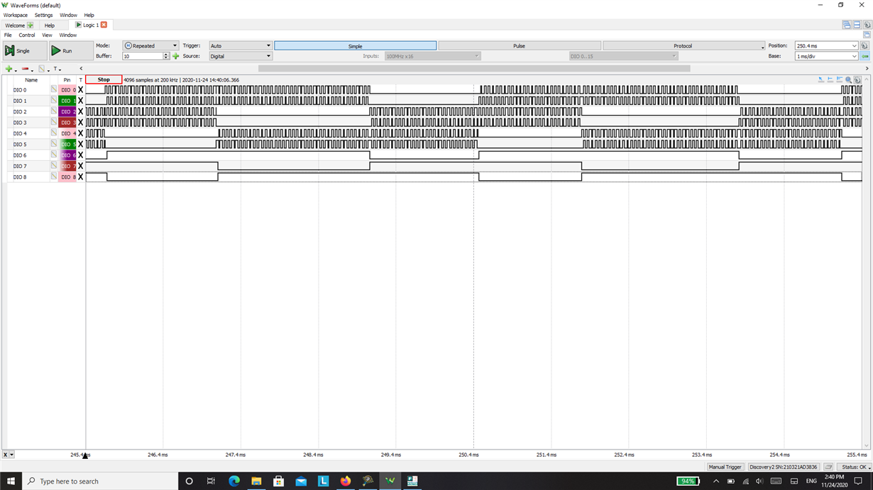
the first thing I tried to input (complementary bipolar pwn and the complementary low side fixed) synchronized with reset input sequence as following
the dio 0 to pwm A , the dio 1 to pwm B ,the dio 3 to pwm c and dio 6 to reset A, dio 7 to reset B, dio 8 to reset C.
as mentioned in the drv8332 datasheet page14.
and the motor not spinning just random movement in two directions.
I tried to debug and changed the sequence many times to different pwm schemes and no chage.
I tested the functional testing mentioned in figure 10 page 18 in drv8332 data sheet.
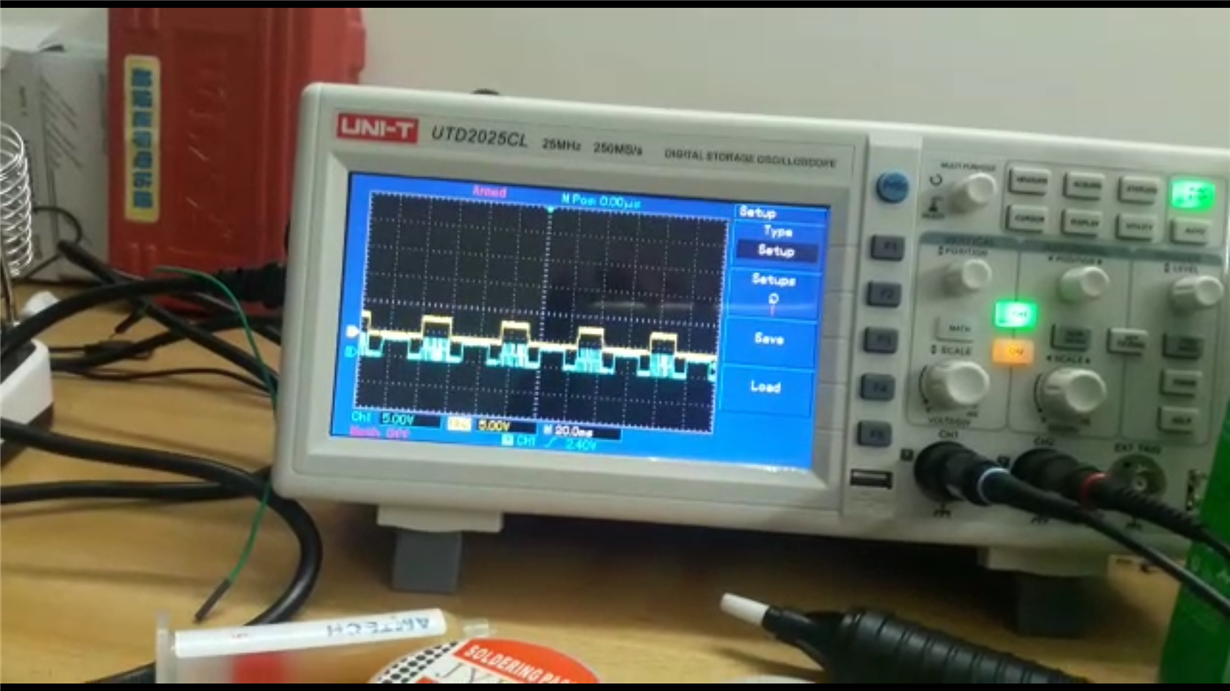
and I got that when pwm of any phase is high and the corresponding reset is varying I got that:
the yellow was the output and the blue is the reset while pwm is high.
the unrecognized is the output when the reset is zero why it is getting this curve.
the last thing I run the drv8312 and the TMDSCNCD28069ISO control card with the ti DRV8312GUIv5 I run the motor and noticed that:
-the pwm signal is mapped to reset pins of drv
-and the 1 and zero sequence is applied to pwm of the drv
the yellow is the pwm and the blue is the reset.
and I can't understand that why and I noticed also the back emf on the output pins maximum volt is 12 while I run the pvdd by 24 volts from the adapter.
so that I need to know what is the level of back emf to know the commutation or to ensure the the information that I have it's the dc us voltage/2.
I need your support to be able to drive the motor and understand why this unexpected decaying volt appearing on the emf/output
and understand the correct sequence to drive the motor with drv8332/8312 and the correct level and considerations of back emf .
and the idea of the sequence that ti used to drive the motor in control card.
Thanks in Advance.


