Other Parts Discussed in Thread: DRV8306, , DRV8316, DRV10987, DRV10970, CSD88584Q5DC, LMD18200
Hi,
I'm new to BLDC motors and recently posted my first question re: sensorless BLDC control here:

Based on the helpful responses from Matt Hein I then decided to try out sensored trazezoidal control as a starting point instead - using the DRV8306.
I now have the DRV8306EVM board and have started testing, however I'm having an issue getting the motor to spin. When I slowly turn up the speed using the pot, the rotor just moves slightly sometimes and oscillates. If I try turning speed up higher, I can see high current draw on the PSU supplying VM (so I haven't turned it up very far yet).
I photo of how the DRV8306EVM is set up is below.

NOTES:
Hall effect connections
- My motor uses Honeywell S41F sensors, which are single ended, current sinking and require supply voltage min of 4.5V.
- So I have removed jumper JP1 and supplied 5V to JP1-2 (RED wire) and also connected 0V from the 5V PSU to HGND (GREEN wire)
- RED and BLACK wires connected to hall connections terminal are HPWR and HGND respectively, then BLUE wire is Hall A, YELLOW is Hall B and WHITE is Hall C
- Switch S3 is in the Sin position for single ended hall signals
- When I rotate the motor manually, each hall input (A+, B+, C+) changes between 2.4V and OV depending on rotor position. [NOTE: It's a 8 pole (4 pole pair) rotor]
Motor connections
- A = RED wire = Phase U
- B = BROWN wire = Phase V
- C = G/Y wire = Phase W
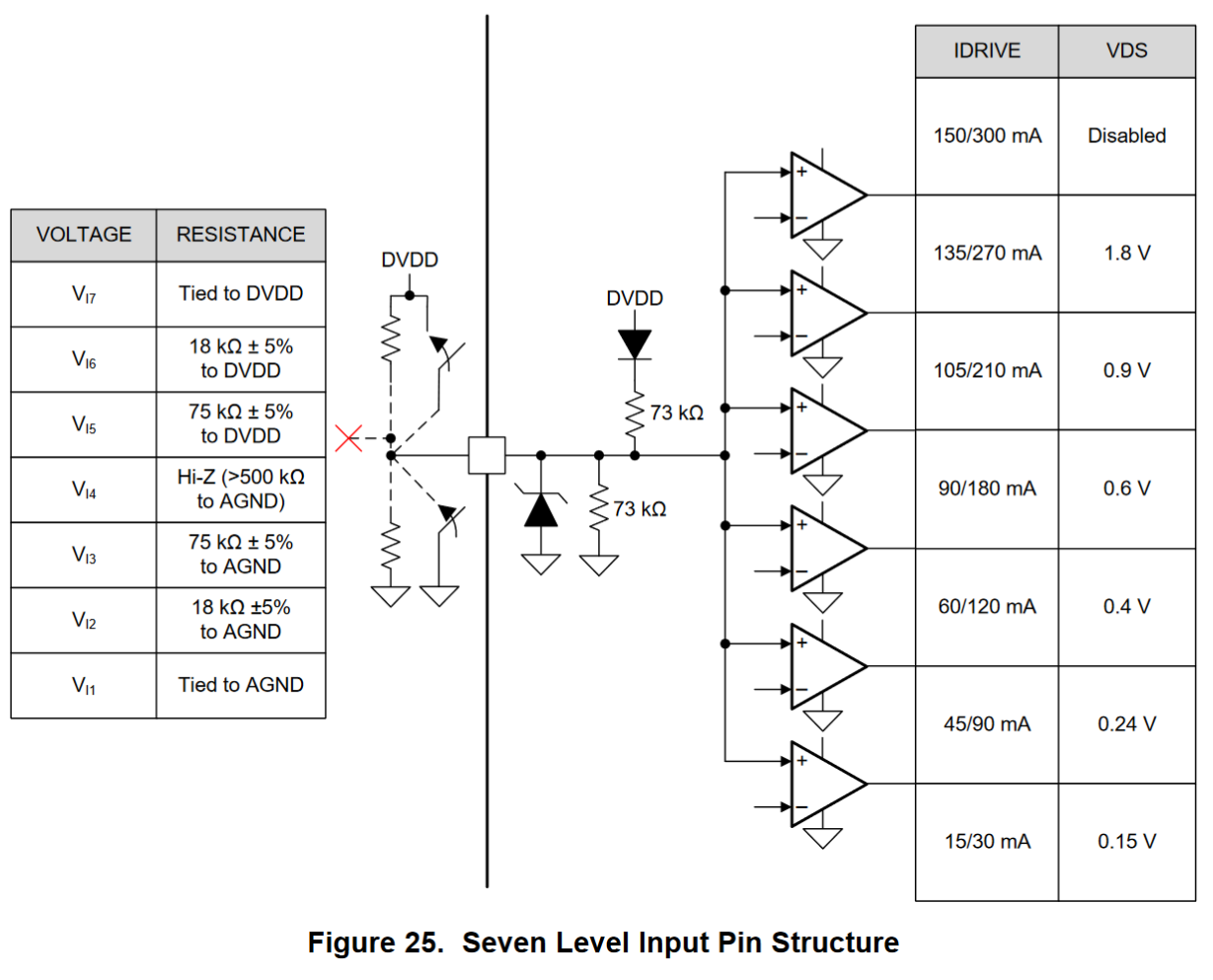
IDRIVE and VDS jumpers
- The DRV8306EVM User Guide mentioned that default setting for these is no jumpers, so I have followed that. Not sure if that's the best starting point though?
Other
- VM = 24Vdc
- Motor is currently under no load. It will eventually drive a pump head, but that is removed and just free spinning at the moment....well at least I'm hoping to get it free-spinning! :)
- I have tested motor using another DEMO board I have here (from a different supplier), was able to get it spinning ok - so I think the motor is ok.
As mentioned, when I power up the system then slowly turn the speed adjust pot - the rotor sometimes moves slightly then stops, and vibrates / oscillates in that spot. Other times it looks stationary, but when I hold the rotor I can feel the oscillation. The rotor also feels 'locked' / difficult to turn if I manually try to rotate it when in this condition. Also as noted, if I turn the speed up further - I can see high current draw on the supply. The motor pulls around 0.6A when free spinning in this unloaded condition (using different demo board), however current draw as over 4A when I tried turning up speed slightly using DRV8306EVM (so I haven't tried turning it any further).
Unfortunately I don't have a scope currently, but can get one if that helps find the issue.
Any ideas on what I've done wrong or any other input would be great - thanks!