This thread has been locked.

If you have a related question, please click the "Ask a related question" button in the top right corner. The newly created question will be automatically linked to this question.

DRV8308: DRV8308 operating modes

Part Number: DRV8308
Other Parts Discussed in Thread: TPS54061

In my design a DRV8308 is driven by a microcontroller on a very compact 4-layer pcb.

The motor is required to spin from 400 to 7700 RPM open loop, and the speed reference

is entered through the speed register. The max current required by the motor during operation is <2A

and the board is supplied at 28Vcc.The +5V to the hall sensors and microcontroller are supplied

by a TPS54061 switching regulator. Mosfets used are NTMFD5C674NLT1G.

I use the internal clock generator.

I am having a hard time in having the motor spinning smoothly without tripping the faults on the driver.

In a couple of cases the DRV8308 burnt out for apparently no reason....

At the beginning of the speed ramp the motor is run with 3 hall sensors, then when the !lock signal goes low I move to

single hall 120° mode. Some questions:

1 should I limit the frequency I update the speed register (the speed reference on microcontroller comes from an analog input).

2)-How can I know if the speed increase/decrease is too steep? Should I control the speed slew rate? What is the

correct program flow when the !lock signal is lost because of excessive speed change or when the speed is too low to keep

the lock logic working?

3)- Is it correct to use the Syncrect bit on and the brkmod bit on in order to keep the

Bus voltage under control, avoiding that a sudden stops cause a surge on Vbus during

regeneration?

Thank you for your help.

Gian Paolo

  • Hi Gian,

    Thanks for your question!

    We are having severe inclement weather in Dallas and multiple team members are without power. Please be patient with our response here.

    Thanks,

    Matt

  • Hi Gian Paolo,


    Thank you for post! In order to determine if the speed increase/decrease is too steep you will need to monitor the Vbus voltage as you decrease the speed command. If the speed changes too quickly for your system, then you will see a rise in the Vbus voltage. If the speed is increased too quickly you will see a sag in the Vbus supply.

    To answer the second part of your second question: when the !lock signal is lost, such as when there is a speed change, the system will switch over to standard 3 hall 120 commutation. Once the system resumes the appropriate speed and the !lock signal appears, then the system will resume single hall 120 commutation

    The Synrect bit won’t prevent surging on Vbus. The primary benefit of Synrect is to improve the efficiency of driving the motor. The brkmod bit doesn’t help prevent the bus voltage from surging during speed changes. Brkmod comes into play when the break pin is applied to stop the motor or when the motor drive is disabled. For regular speed decrease it is necessary to monitor Vbus to make sure that there isn’t a large increase in the voltage of Vbus.


    I have a few questions:

    1. You mentioned that sometimes the motor driver will throw a fault during operation. What fault code are you reading?
    2. After the motor achieves the desired max operating speed does it run smoothly? Or are you still experiencing issues while operating at a constant speed?
    3. What is the iDrive setting you are using? If your iDrive is too high for your mosfets that can negatively affect the performance.
    4. What is your speed change tolerance for lock? This is set in address 0x03 bits 14-12.
    5. What is your MOD120 register settings?


    Regards,


    Anthony

  • Hi,

    when the fault happen I read 0x18 in the status register (CPFAIL and UVLO). What I don't understand is why I get Undevoltage even when I REDUCE the speed......

    At the max speed it runs very quietly, but it gets rough when, due to a change in the load, it unlocks from single Hall 120° mode. In basic mode at max speed I would experience

    a huge current comsumption even at no load (>1A against 130mA when locked). The problem is: until it is locked there is no way I can advance or delay the hall signals...correct?

    The Idrive value now is 4, I played with it but it seems it's not making any difference to solve my issues.

    The speed threshold is set to 5.

    The MOD120 at the moment is 2000.

    Monitoring the Vmotor could be a problem at this stage of the design.

    The fact is my board should substitute with much higher performance level a ridiculous 2-layer 8 bit microcontroller (nearly obsolete) board with direct P-N fet drive without

    Vmotor and fault monitoring (apart from Imax), but the latter is working far better than mine with a specific brushless driver, 4-layer pcb and far more expensive electronics......

    If required I can send privately the schematic.

    Regards,

    Gian Paolo

  • Hi Gian,


    Thank you for your reply! Have you programmed the OTP memory? If you haven’t then when the device is powered up in SPI mode the default register settings for the fault register is 0x18. This can be cleared by writing zeros to the fault register. I want to make sure that the fault register readings you are getting are a result of the actual fault and not simply a result of the default settings.


    You are correct: The ability to advance the commutation in relation to the hall signal is not available in standard 120 commutation.

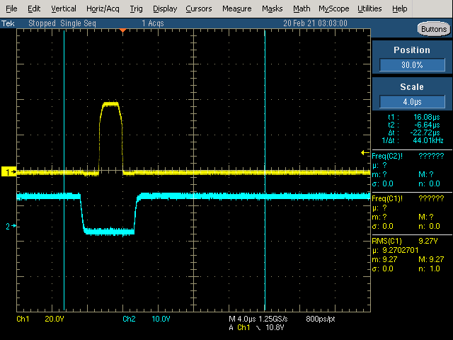
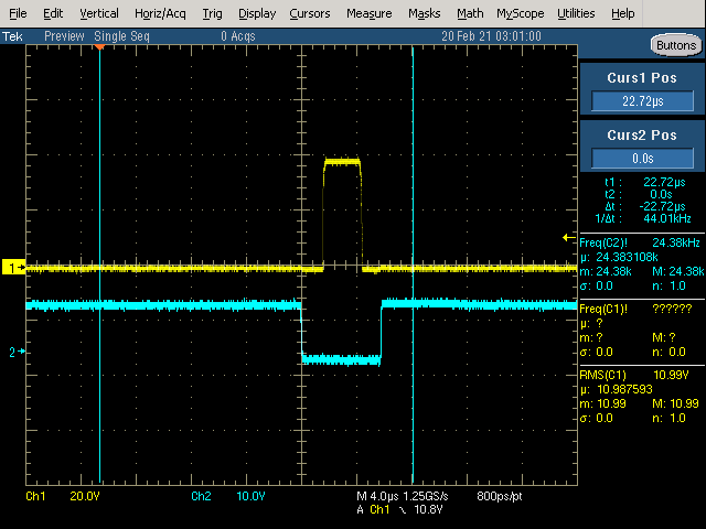
    Can you send a scope plot showing the gate to source high side and low side signal for one of the phases? The Qgd for the transistor you are using is quite small (1nC), so with the current Idrive setting the turn on time of the Mosfets is too quick and can cause ringing on the gates. For the 90mA Idrive setting the turn on time is equal to 1nC/90mA = 11.1nS. For most systems 200nS turn on time is considered fast, and depending on the PCB design 200nS may be too fast for the system to handle. Even with the lowest Idrive setting for your system the turn on time would be about 100nS, and will probably still cause significant ringing on the gates. If you see significant ringing on the gate you could add a 1-5ohm resistor to the gates to help reduce the Idrive even more.


    Regards,


    Anthony

  • HI,

    I don't have programmed the otp and at boot up I do reset the status register.

    Any idea of why the power consumption is so high in standard 120 commutation? Wrong hall placement?

    The motor maunufacturer developed the driver board too, I hope it wasn't done intentionally......

    I think hall polarity and delay bit is correct, otherwise the motor would not spin at full speed, correct?

    Tomorrow I will take some screen shot  of the gate signals and I'll send them to you.

    What I find particularly bad is that still the DRV8308 at times burns out..... and I am sure it is not the overvoltage

    on the VM pin!.

    On a previous design stage (and post) I was using the internal regulator to power up the halls and microcontroller,

    at times the driver would burn out (fixed consumption at 20mA and no activity whatsoever including lack of voltage on

    charge pump) but I was told it could be a surge on the enable pin limited to 5V with a resistor and a zener diode + capacitor from the

    VM bus. Now in the new design a switching regulator is providing energy to the halls and microcontroller, and when it burns

    out the consumption goes to 100mA and the driver gets very hot. The halls are always powerd up but they are OC and I don't

    think the 4.7K pullup resistor could harm the driver when the micrcontroller is pulling down the enable pin.... infact the datasheet

    is contradictory because it says non to power up halls when the enable is low, but somewhere else it says the halls must be powered

    up when the driver starts otherwise it could find them in an illegal configuration... any clue on why is burning out?

    Gian Paolo

  • Hi,

    I managed to get 2 pictures with Idrive=1 and Idrive=4, dead time=6

  • Hi Gian,

    Thank you for your reply and the additional information!

    I will try to get back to you tomorrow, but to start off I think it would be helpful to see an oscilloscope plot that shows all three hall outputs during operation when the motor is in normal trap 120 commutation. Additionally, it would it be helpful to see the plot of one of the phase currents with respect to the hall outputs. 

    Regards,

    Anthony

  • Hi,

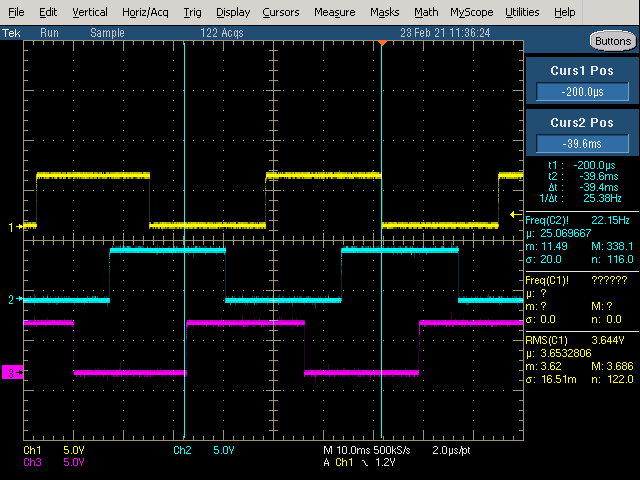
    I managed to get some screenshot from the oscilloscope.

    First, the  3 hall signals, they look absolutely fine to me (infact the original driver works ok with the same motor)

    Then a screenshot of 1 hall and 1 phase of the original driver:

    If I don't set the polarity bit and delay bit on DRV8308 I have a similar waveform:

    The problem is with this hall polarity I can't have the DRV8308 to lock IN. Every time It tries to lock it seems it is "kicking back "

    and start again, even if it doesn't stop.

    Then I set the hall polarity bit and delay bit to 1, this is the unlocked status waveform:

    And this is the locked one:

    Unfortunately once again the transition from unlock to lock is not smooth and I run into the problems I told you about previously.

    I replaced the original mosfets with NVMFD5873NL, these have 8.8 nC of Qgd but nothing changed.....

    Any Idea?

  • Hi Gian,

    After reviewing your waveforms, I have a few comments and questions:

    As you mentioned, it looks like the motor performs better with the hall polarity = 1 compared to when the hall polarity = 0. Do you have the motor datasheet? We can double check some information on it that might be helpful.


    The delay bit doesn’t affect the motor operation until the device is operating in the Lock mode using single hall commutation.

    The waveform of the 3 hall sensors seem to be operating properly. Was that graph taken while the device was in lock mode? Or was that during regular 3 hall 120 trap commutation?

    Based on the second to last waveform you provided it looks like the length of time that the driver is in high-Z mode is much shorter than expected when it is not in lock mode. In order to help us further understand what is going on, can you provide a waveform showing all 3 hall phases plus the high side source of one of the phases during regular 3 hall 120 commutation? Also, if you could label the waveform to show which phase corresponds to which signal that would be greatly appreciated.

    Regards,


    Anthony


  • Hi,

    the motor is a Vishan device, PN EC3260S-2406, 24V,6600rpm.

    I tried to attach the pdf file, but no success.

    I don't understand the question about the halls, what is the relevance if the screenshot has been taken when locked or not locked?

    In both cases the speed is constant, but the power consumption is much higher when it's unlocked even if there is very little load

    on the motor ( a 6 to 1 gear is the only "load" applied at the moment).

    Should I program the drv8308 in basic mode and then move to single hall 120° after the first time it locks,

    or can I program it right out of reset for single hall and then it does the transition automatically when it reaches a reasonable speed?

    Is it expected than even slowing down the motor when it goes back to basic mode the transition is not smooth?

    Should I expect that a sudden change in load would unlock it temporarely? If the transition is so rough don't think it's acceptable

    for my application..

    I find very weird that, in order to lock properly, the hall polarity must be opposite to the one I see on the original driver......

    see again the pictures!

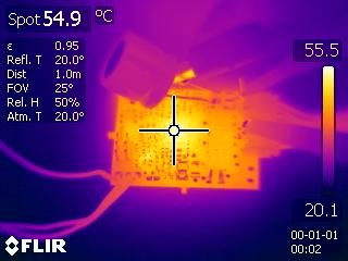
    I also took a thermal screenshot of the driver, considering it is only powering up the fet gates and the internal logic

    (microcontroller and halls are powered up separately with a switching regulator) it seems pretty hot to me...

    current is around 80mA and Vmotor is 28.5.(pwm frequency is 25KHz, I drive =0, Tdrive=1, dtime=6).

    I will try to do the measurement you required, I have a 4 channel 500MHz oscilloscope

    but I don't know if I have 4 probes....

    Regards,

    Gian Paolo

  • Hi Gian,

    Thank you for your response. I will get back to you either later today or tomorrow.

    Regards,

    Anthony

  • Hi Gian,


    The reason I wanted to know whether the hall scope plot was taken while in single hall or 3 hall mode is because if the device was not in lock mode then it seems that the roughness in the operation of the motor might be reflected in the hall outputs.

    When a sudden change in load occurs, it is expected to unlock since the load change will result in a speed change and cause the parameters for lock to no longer be met. So, this would cause the motor to unlock temporarily until the motor reaches the expected performance, and once all the lock conditions are met again then it would go back into lock mode. I appreciate your patience as we work to obtain smoother operation for your motor when it is in 3 hall 120 commutation, as well as see if we can significantly improve the transition from locked to unlocked operation.

    You can program the device right out of reset for single hall 120 commutation, since you are essentially telling the device what to do once it reaches the lock state. The transition will happen automatically once it reaches the lock state.

    Unfortunately, the motor datasheet doesn’t have any data on the hall sensor waveforms. I had a discussion with a coworker about your situation and it seems like there could be a possibility that your particular motor is supposed to use the hall signals as noninverted, but the motor may be driven too hard which is why it is unable to lock in that state. When you have the device operate with inverted hall mode it is still able to roughly commutate, but since it is inverted it results in higher current consumption and rough operation. To test this theory could you run the motor at a much lower rpm and see if it will lock properly while using noninverting hall signals? Could you repeat this procedure using inverted hall signals?

    One way to verify whether you need to use inverted hall signals or not is by performing the test outlined in this FAQ (3) [Resolved] [FAQ] How to Ensure Correct Alignment of Hall Sensors and Your Motor - Motor drivers forum - Motor drivers - TI E2E support forums and then if you see that either the hall states or the back emf is inverted compared to what is shown in the picture, then that means your motor needs to be driven with the hall signals inverted. If you perform the test and it looks the same as the waveform shown in the picture, then the motor should be driven as is, without inverting the hall signals.

    The motor driver seems to be a litter hotter than expected. Device heating can be caused by multiple factors, including PCB layout. If the grounding paths for the device are not designed optimally, then this can result in the board not being able to sufficiently distribute and dissipate the heat and will result in the device heating up more than is normal. I have included an article about best layout practices that includes a section on how to best design the grounding paths for a motor driver PCB to reduce heating. https://www.ti.com/lit/an/slva959a/slva959a.pdf Hopefully as we work through a solution to reduce the rough operation of the motor we may see a decrease in operation temperature. 

    One thing that is of some concern is that the supply for the motor is 28.5V, but the motor is rated for 24V. Although the average voltage due to PWM might not exceed the rating of the motor, it is still a little concerning to use that high of a voltage supply especially with the possibility of voltage spikes during operation.


    Regards,

    Anthony


  • Good morning.

    I noticed one weird fact: when I set the hall polarity bit on register 6 the motor spins in the opposite direction, is that normal?

    The power consumption is very high in basic mode even at low rpm whether the hall polarity is set or not. When it is locked

    I get the lowest consumption with no load with the advance value around 120. As stated previously in this condition the motor

    runs as smooth as the original board even at max speed (but with no sudden change in speed or load).

    I thinks that while there is so much difference in current consumption between the lock and unlock condition I don't think

    there could be a smooth and safe motor operation...

    If I don't set the delay bit the motor rotor keeps hiccupping.

    If I don't set the syncrect bit in reg0 the power consumption doubles (from 60 to 120mA at 1200 rpm and no load).

    I didn't have the time to perform the steps suggested to check for correct hall alignement, but if this could be quite far

    from optimal is there a chance I can use DRV8308 for such a motor since in basic mode there is no way to compensate

    for it?

    Finally could it be that the original motor pinout from which I started the design was reporting wrongly the phases and halls order?

    What would it cause if the order is not correct?

    Regards,

    Gian Paolo

  • Hi Gian,


    The fact that the motor spins in the opposite direction when you change the hall polarity bit is not surprising, since you are inverting the hall signals and effectively changing the commutation sequence.


    The fact that you get the lowest power consumption with no load with an ADVANCE setting of 120 is concerning to me. That would be about 12.5% advancement of the commutation compared to the duty cycle of the hall signal, which is quite high and leads me to think that there could be significant hall misalignment which would explain the issues you are having when operating in regular 120 commutation which doesn’t offer the ADVANCE feature. Can you run a test by setting ADVANCE to 0 and see if it runs with higher current consumption (comparable to what you are seeing when it is not in locked mode)?


    I am not surprised at all that you are seeing issues when you don’t set the delay bit, since the delay bit tells the motor whether to commutate before the hall signal (based on the ADVANCE value), or after the hall signal (based on the ADVANCE value)


    Operating the device in synchronous mode will turn on the low side FETs during the off cycle of the PWMs, which results in the current being able to more efficiently circulate through the FETs/motor, so the motor doesn’t have to draw as much current from the supply. The thing that is surprising is that you are noticing a 2x change in current consumption, from asynchronous vs synchronous, which seems more drastic than we might expect. What is the inductance of your motor?  


    If the motor phases and hall phases are not connected in order then that would at a minimum cause rough operation of the motor, and may even cause the motor not to spin. That is definitely a possibility to explore. It would be worth a try to see if you can change the order of the halls to see if you can verify if the halls and phases are corresponding properly. Make sure you try both the inverting hall and noninverting hall settings to see if you can find a combination that operates properly.


    Regards,


    Anthony


  • Hi,

    I think I found the problem myself: the 3 phase sequence was wrong compared to the hall sequence in the wiring diagram that was given to me to do the new driver!!!!

    Obviously in lock mode the system was able to find the right phase with a single hall (giving a great advance), but as soon as it would unlock it would go back to 3 halls system and it would mess up!

    Now everything seems to be ok, the advance value is mininum and the idle current is comparable in lock and unlock mode!

    Garbage-in garbage out looks to be the lesson for this issue, when you start a project with wrong data even a simple task would become troublesome.....

    Regards,

    Gian Paolo

  • Hi Gian,

    I am glad you were able to figure out the issue! That definitely explains the issue. Please let us know if you have any other questions.

    Regards,

    Anthony