This thread has been locked.

If you have a related question, please click the "Ask a related question" button in the top right corner. The newly created question will be automatically linked to this question.

DRV8711: DRV8711 failure mode

Part Number: DRV8711
Other Parts Discussed in Thread: CSD88537ND

We are experiencing DRV8711 failures (gate drive output shorts) in a similar fashion to the question I have linked mine to.

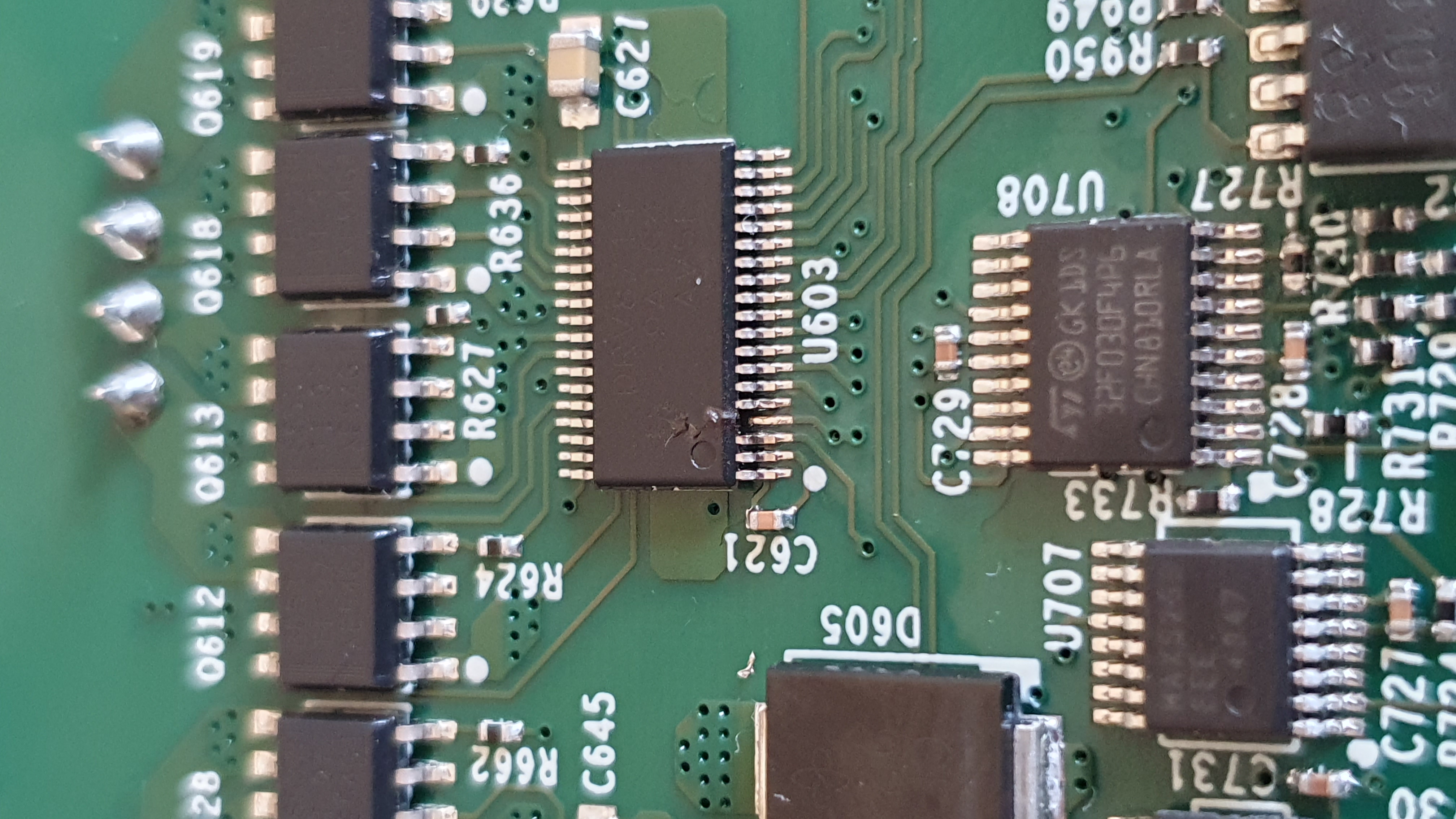
We have a single PCB with 6 DRV8711 + CSD88537ND stepper motor drives on. We have been using this design for a couple of years with no real issues (with the drives at least) . Recently though as part of some optimisation work, we have been 'cooking' some stepper motors which has resulted in their windings become melded and reducing their measured resistance from 1.4 nom to less than 0.5 ohms - I have yet to inevstigate how much of a dead short they are - in which case there may be zero inductance too which is not helpful.

Connecting one of these motors to a drive which is working results in SPI faults (we read back what we write to check that data is being correctly loaded). Upon further investigation it seems that the DRV8711 is completely dead - no response on SPI at all. Checking the FETs I noticed a dead short from Gate to Surce and Source to Drain on one of the top FETs. Removed the top FET and the shorts were still there necessitatng the removal of the 8711 itself.

I am curious about the failure mode of the 8711 we're seeing here since I have always viewed the driver being somewhat removed from the real power of the drive since that's handled by the FETs, but something's not right. What am I missing?

VM is 42V in our application. Circuit below.

  • Hi Jon, Thank you for posting to the motor drivers forum. I have a couple of questions: Is the power supply of the H-bridge shared with the DRV7811? Can you send the schematic again? I’m not able to view it from my end.
  • Yes the H-bridge power rail and VM of the DRV8711 are one and the same.

    Apologies for the schematic drop off, I thought I’d cut and paste, I’ll do that when back in the office.

    Thanks

  • John, No worries. Please attach the image as a file when you send it again.
  • I have more information to add to this report.

    We have a motor which has low resistance windings due to thermal abuse. When connected to one of these drives, the DRV8711 fails which we first see as an SPI readback fault. On further examination, we find that there are two detectable failure modes (when probing various pins):

    1. Top FET has Source and Gate shorted (AOUT1 - A1HS)

    2. Bottom FET has Source and Drain shorted (AOUT1 to GND?)

    On a particular board, 3 drives were exposed to this motor and the failures were

    Driver 1 - A1 output bottom FET fault / B1 output top and Bottom FET faults

    Driver 2 - A2 output top and bottom FET fault / B1 output top and Bottom FET faults

    Driver 3 - A1&A2 output top and bottom FET fault / B1 output top and Bottom FET faults

    FETS were removed and faults remained. A DRV8711 was replaced and the FETs returned after which all was good (with a good motor)

    In addition, after the motor had been removed from all drives, but power remained on with no motor loads, driver 3 (u603) experienced a fuse blow type failure resulting in this - (Vm pin event causing the package to crack at that point!)

  • Hi John,

    Thank you for providing the additional information.

    I require some more time to look at the information you have shared and to do further research on your issue. Expect a reply from my by 2/19 or earlier.

    Thank you for your patience.

  • Hi John,

    Damaged motors have lower resistance and inductance of windings as you have already pointed out.

    Inductance and VM has an influence on how fast current rises up during PWM ON period.

    Value of winding inductance would be helpful to determine what we can expect during operating such motor.

    It would be worth of trying to run these damaged motors with much lower VM like 12V.

    Setting OCPTH and OCPDEG values to possible minimum might help as well to save DRV8711.

    If board can run at lower voltage then it would be possible to measure voltages on switch nodes, VM and Mosfet gates

    with an oscilloscope as well motor current (current probe needed). Then it should be possible to look for any voltage spikes

    and ringing. For voltage measurement probe 10x with spring hook may be used.

    If voltage spikes or ringing is a problem then it might be possible to improve PCB layout or add some components to limit value 

    of these spikes or ringing.

    Best Regards,

    Grzegorz

  • Thanks for sharing your experiences, Grzegorz! These are excellent debug suggestions.

  • Many thanks for taking the time to share your insights, I'll be getting some bench time with this again soon and I'll dig into this some more.

    Appreciate your suggestions,

    John

  • Hello John,

    Please let me know once you complete the experiments suggested by Grzegorz. Thank you for sharing this information Grzegorz!

    I noticed in the schematic that there is no local bulk capacitor on VM. It is recommended to place a bulk capacitor on the VM line to help smooth out the VM bus and to source the current to the load. Do you have a bulk capacitor in your design?

  • Hi Pablo,

    Thanks for taking time to review this... a perfectly valid question regarding Vm capacitance.

    1. Each of the 6 drives has a local 10uF / 75V cap located in its vicinity - one for each drive

    2. A further 2 off 220uF / 100V DC capacitors are located in the vicinity of all 6 drives

    3. 2 off SMCJ43A TVS diodes are located in the vicinity of the drives

    I will provide further feedback when more experiementation is complete.

    Thanks again.

    John

  • Hi John,

    Thank you for the clarifications.

    Having bulk capacitors near the power entry point of the board and near the IC is crucial. These capacitors help smooth out any noise in the supply line and also help provide the high in-rush current the motor requires during start-up and stall.

    I recommend reading this appnote to learn about best practices for layout design of motor drivers. I'm not saying that the problems you are having is due to layout but it doesn't hurt to double check your layout once again.

    Please update me once you complete the tests.

  • Hi John,

    Any updates from your side? Were you able to figure out the root cause of the issue?

    Let me know if you require further assistance.

  • Hi John,

    I have not heard back from you so I will assume that your issue has been resolved. If you require further assistance, please reply to this post.