Other Parts Discussed in Thread: , TPS54160, TM4C123AH6PM
We have been in volume production for over 2 years, using the DRV8301.
On a recent batch of 12 units, 3 units are behaving strangely.
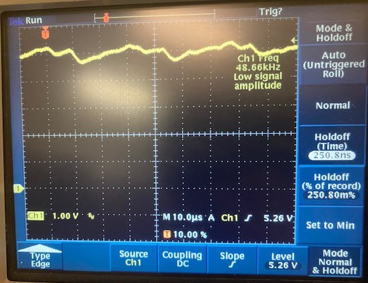
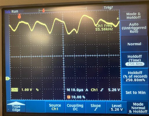
Upon close inspection, the pre-driver output for 5V generation, out from pin 50 and pin 51, has a ripple of +-0.8V about the 5V line at startup, then stabilizes.
Good units do not have this issue. We have not changed the BOM or the PCB !!!
I have read the spec, there is no mention on how to calculate the RC combination on pin COMP, and there is also no information on how to calculate the resistor divider for pin VSENSE.
I looked at your design "BOOSTXL-DRV8301_SCH" and you use the same COMP RC combination as shown in your data sheet.
Note, "BOOSTXL-DRV8301_SCH" produces 3.3V from the DRV8301, on our design we created 5V. I do not know how the COMP pin would change because of this.
The previous designer used a different RC combination {39pF || (28k + 6800pf)} your designs have {120pF || (16.2k + 6800pf)}
Can you tell me what the VSENSE voltage is meant to be when operating? Equations would help.
We have been in volume production for over 2 years, using the DRV8301.
On a recent batch of 12 units, 3 units are behaving strangely.
Upon close inspection, the pre-driver output for 5V generation, out from pin 50 and pin 51, has a ripple of +-0.8V about the 5V line.
Good units do not have this issue. We have not changed the BOM or the PCB !!!
I have read the spec, there is no mention on how to calculate the RC combination on pin COMP, and there is also no information on how to calculate the resistor divider for pin VSENSE.
I looked at your design "BOOSTXL-DRV8301_SCH" and you use the same COMP RC combination as shown in your data sheet.
Note, "BOOSTXL-DRV8301_SCH" produces 3.3V from the DRV8301 and our design we created 5V. I do not know how the COMP pin would change because of this.
The previous designer used a different RC combination {39pF || (28k + 6800pf)} your designs have {120pF || (16.2k + 6800pf)}
Can you tell me what the VSENSE voltage is meant to be when operating? Equations would help.
Please take a look the attached schematics.


