We have a stepper motor driver board that uses the DRV8711. We have produced several hundred of these boards without issue. The design uses a 50 milliohm sense resistor. Until recently, we have been using a Stackpole CSM2512FT50L0 for the sense resistor. It was recently changed to a Yageo PA2512FKE7W0R05E due to stocking issues. Both resistors are 50 milliohm 1% in a EIA-2512 package. The new resistor (Yageo) is rated for 2W while the old resistor was rated for 3W.
The stepper motor current is 2.8A and the power supply voltage is 36V. The power dissipation is (2.8)^2 * (0.05) = 392mW so either resistor should be fine.
We have found that boards built with the Yageo current sense resistor cause the attached stepper motor to whine and screech noticeably compared to the Stackpole resistors.
The PWM waveform on the stepper coil for boards built with the original resistors shows a clean 59kHz square wave. The same measurement on the boards with the new resistor shows a lot more jitter on the waveform. Both measurements were taken with the motors idle.
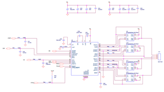
I have attached a copy of the schematic and some oscilloscope screen captures:
StackpoleChopperSignal.png - Stepper motor winding voltage using the original sense resistors. Clean, 60kHz square wave.
YageoChopperSignalPersist.png - Stepper motor winding voltage with the new sense resistor. Unstable duty cycle captured with scope display on persist.
YageoChopperSignalPersist.png - Stepper motor winding voltage with the new sensor resistor. Unstable duty cycle captured in single-shot mode showing runt pulses.
The DRV8711 settings are listed below:
Toff = 6.5us
DTIME = 850ns
TBLANK = 1us
Decay mode = 0x011 (Mixed)
Adaptive blanking enabled
IDRIVEP = 50mA
IDRIVEN = 100mA
TDRIVEP = 500ns
TDRIVEN = 500ns
OCPTH = 500mV
OCPDEG = 1us
Any advice on what characteristics of the sense resistor could be causing these issues would be greatly appreaciated.
Thanks for your support.