This thread has been locked.

If you have a related question, please click the "Ask a related question" button in the top right corner. The newly created question will be automatically linked to this question.

DRV110: Hold current much higher than calculated

Part Number: DRV110

We're doing a low-voltage/relatively high current design using the DRV110 part. For some reason, the hold current is over 6amps, rather than the calculated 1.5A expected. Could it have something to do with the values of C3 and R8? If so, how should those values be calculated?

Here's the schematic:

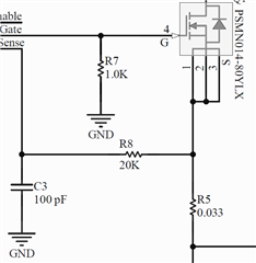
...and a close up of R5 & R8, in case it's not clear:

Any help is very much appreciated!

Thanks,

Calvin

  • Hi,

    Thank you for your interest in DRV110. Sorry for our late response. Due to system issue, we could not reach this post.

    R5 and R1 setting looks good to have 1.5A. My suggestion is

    -Try to reduce R8 (e.g 10ohm)

      If DRV110 do not see voltage on Sense pin ~150mV, do not turn off the external FET. R8/C3 filter may be too strong.

    -Try to increase R5 for just test and get higher voltage on Sense pin. (e.g 0.1 ohm). Please refer page 10 for Vsense waveform example.

    regards

    Shinya

  • Hi Shinya,

    Thank you very much for your response! I suspected that the RC filter (R8+C3) adds too much phase delay. Thank you for confirming that suspicion. Is there some kind of calculation you used to arrive at 10 ohms? If so, can you share the math with me?

    It's difficult to pull the R5 resistor off, but we'll give that a try if reducing R8 doesn't help.

    Ordering the parts. We'll give it a try as soon as they arrive. I'll keep you posted!

    Thanks,

    Calvin

  • Hi,

    Thank you for sharing your  plan. 10ohm is just example to see the difference from your original settings. It is OK to use higher value to have proper filter settings if high current issue goes away. Vsense waveform is important for DRV110 to control loop.

    regards

    Shinya

  • We lowered the resistance in R8, but that didn't eliminate the problem. What did was using a battery on the enable instead of a power supply. I think what's going on is that turning off so much current is causing a voltage spike because of inductance on the power line. This causes ground to bounce all over the place, which causes the enable to look like it's being turned off and back on again.

    We're working on reducing that voltage spike with a redesign.

  • Changing R8 didn't resolve the problem. Putting a battery across enable and ground did.

    Here's what I think is going on: enable goes high; current starts building up through the solenoid; when the transistor turns off the first time, there's a lot of current going through it. The fly-back diode protects the solenoid from the voltage spike, but there's no similar protection for the energy in the power cables. So a voltage spike happens. This causes the ground reference to bounce, which made enable look like it had gone low and high again.

    We're redesigning the circuit to handle the voltage spike. We'll see how it goes!

    Thanks,

    Calvin

  • Hi ,

    Thank  you for sharing update and understood you are going to redesign the circuit to reduce voltage spike. Hopefully it will work. 

    regards

    Shinya