Other Parts Discussed in Thread: DRV8874-Q1
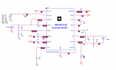
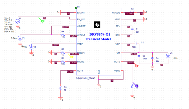
I am using the spice model to simulate the DRV8876 in PWM mode. The sleep input is high as is IN1 and IN2 is toggled to create the PWM timing. PMODE is pulled up with a 10K resistor and IMODE is pulled down with a 62K resistor.
Vref is driven to ~1V by a resistor network from 3.3V, 10K pullup and a 4.3K pull down. IPROPI has a 1K to ground to turn the current into a voltage mapping 1 amp to 1 volt. The load is drawing a variable current between 50 and 90 mA. However, when I examine these signals IPROPI has virtually zero voltage on it (993pV) while Vref has the expected 992 mV. The similarity of these numbers was suspicious so I changed Vref to be 1.65V and it adjusted. IPROPI also changed to 1.651nV. I changed the value of the resistor on IPROPI from 1K to 1Meg and the IPROPI current remained at 1.651pA while the voltage increased to 1.651 uV.
Clearly there is a connection between the Vref voltage and the IPROPI current. I've checked my design for an unintentional short by name and these signals are not connected to each other or anything else. Can this be a flaw in the model? The comments in the model would seem to indicate the IPROPI current sensing is functional.
* A. Features that have been modelled
*	1. Control Mode
*	2. Current Senses
I suppose I may have not used the model correctly. The control inputs are set at constant levels and the sleep_n pin starts low and after 100 us is brought high to trigger the mode controls being read. Any ideas?