This thread has been locked.

If you have a related question, please click the "Ask a related question" button in the top right corner. The newly created question will be automatically linked to this question.

DRV8306: With some motors, there are false gate turns on

Part Number: DRV8306

Hi all,

I am having a peculiar problem. With the same driver circuit and three different motors (Thingap  LSI 75-12) only one motor works without this anomaly. 

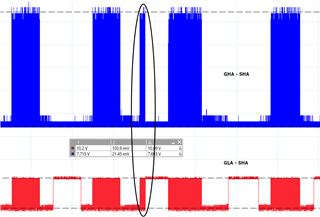
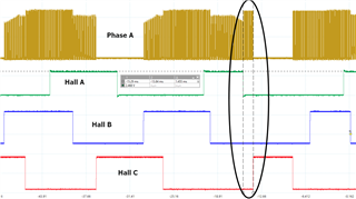
The issue is when I checked the GHA and GLA, I can see in some cycles, the gates falsely turned on. See image attached.

There are no faults reported.

The DIR, BRAKE, ENABLE signals are in correct levels.

What is happening here? 

Thanks,

Kay

  • Hello Kay,

    Hall Sensors

    The DRV8306 is only really as intelligent as the hall sensors when it comes to commutation timing. Can you grab the SHx and all 3 hall inputs on the same plot and see if you can find the hall transition that lines up with this "false gate" activity?

    I say this because the DRV8306 uses 6 stage trap and I assume you are not accelerating in this picture. This means, we expect equal time for all 6 states if the motor is running in a constant and steady state. Its very clear that some of the states are longer than others.

    As a reminder, the 6 stages for a given phase are HIZ, PWM->HS(ON), PWM->HS(ON), HIZ, LS(ON), LS(ON), see table 2 in the datasheet. You should be able to decode what state the device is in based on hall sensor inputs and those signals The waveform makes it look like we transition into another state which is quickly overridden by another state. The GLA- SHA is a strange waveform to take, usually low or high side Gate to Source or high side source to GND are the popular waveforms, so I can't comment on what state we're in without a whiteboard but table 2 should be able to help you out.

    Current limit

    Alternatively, a we're hitting the circuit by circuit current limit and we're PWM'ing the gate instead of keeping the phase on.

    To check this, can you grab the phase ISEN pin and the value of the sense resistor used to calculate equivalent current? We'll compare this with the VLIMIT specification (0.25V typical). 

    Best,

    -Cole

  • Hey Cole, Many thanks for your reply. In fact it was an anomaly in the hall sensor signals. One hall sensor was producing an erroneous output in one pulse. I have raised the issue with the motor manufacturer. Hopefully can be resolved soon. As can be seen below, the Hall-A signal is asserting too late and de-asserting too quickly.