This thread has been locked.

If you have a related question, please click the "Ask a related question" button in the top right corner. The newly created question will be automatically linked to this question.

mismatch between VPROPI and current measure through the motor coil using ammeter

Other Parts Discussed in Thread: DRV8801

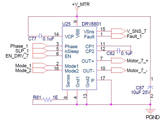
Hi, I have designed a dc motor speed control using drv8801IC, in which phase pin of drv8801 is used as direction input and enable pin as pwm input pin. Every thing is workig fine. The schematic file is as below. I have connected 1ohm resistor to sense pin which in turn allows only maximum of 500mA current through the motor coil. And the VPROPI pin can give maximum of 2.5v for 500mA current. The analog voltage from VPROPI is routed to ADC. The VPROPI is 5 times greater than the voltage across the Sense resistor. Now the problem is, I have connected an ammeter in series to motor coil and the current reading in ammeter is different from the sense resistor reading. Definately it is having difference of 20mA more. Can any body help me out in solving this issue. 

  • If I understand correctly, you are reporting a 4% error in the voltage measured via the VPROPI pin?

    There are a number of contributors to this error, including PCB trace resistance, tolerance of the resistor, and the accuracy of your ammeter.  All these in addition to errors in the gain and offset inside the DRV88001 can easily add up to more than the small error you are seeing.

    The VPROPI functionality is intended to provide an indication of motor current, not a precise  current measurement.  I would anticipate between 5% and 10% error would not be surprising.