This thread has been locked.

If you have a related question, please click the "Ask a related question" button in the top right corner. The newly created question will be automatically linked to this question.

DRV8353: DRV8353 or DRV8301 short circuit protection between two phases

Part Number: DRV8353
Other Parts Discussed in Thread: DRV8301,

Hi team,

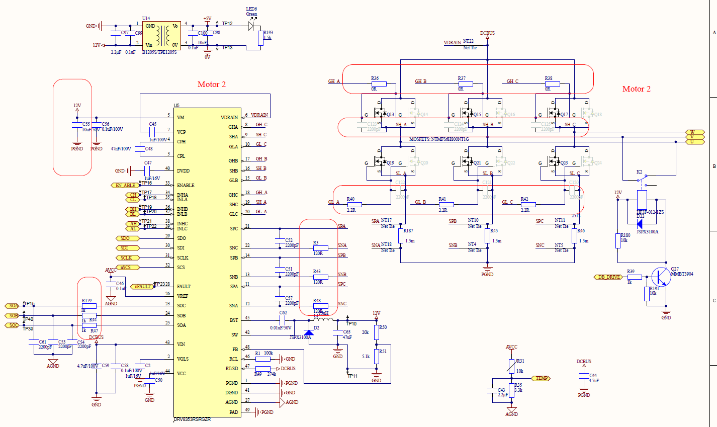
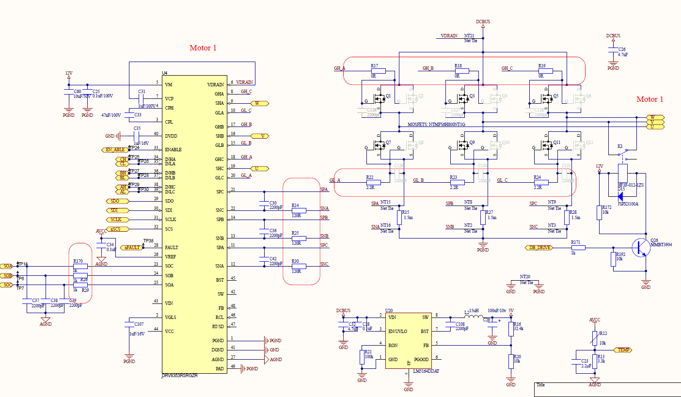
We want to confirm if DRV8353 or DRV8301 have the short circuit protection function between two phase output, could you please confirm that?

Here are the details:

VDRAIN=48V, VM=12V, before power up, we short U to V (or U to W, or V to W). After power up, DRV8353 is broken, and GDUV happens.

Thanks.

Best regards 

Chen

  • Hi Chen,

    Both of these devices have over current protection which helps protect the system against output shorting events. However this protection is based on the VDS of the external MOSFETs (I x RDS) and needs to be enabled and set appropriately for it to function correctly.

    GDUV is normally indicating that the gate drive setting (IDRIVE) is too low or too high. Can you provide the device settings - SPI registers if it is a SPI device and hardware pin configuration if it is a Hardware device? Please also provide the MOSFET part numbers in use. If you have a schematic that you can share, that would be helpful.

    Thanks,

    Matt

  • Hi Matt,

    Thanks for your help.

    Please see the registers and schematic as below.

    Drv8353RS Registers Value :
    Driver Control Register (address = 0x02h) :0x04A0
    Gate Drive HS Register (address = 0x03h) :0x0322
    Gate Drive LS Register (address = 0x04h) :0x0322
    OCP Control Register (address = 0x05h) :0x033D
    CSA Control Register (address = 0x06h) :0x0243
    Driver Configuration Register (address = 0x07h) :0x0000


  • Hi Chen,

    Based on your IDRIVE settings the rise time seems to be slightly high at about 160 ns with a 100mA IDRIVE setting. I would recommend lowering the IDRIVE slightly.

    I noticed that you have C45 rated to 100V, this is not necessary can you could use one rated at 25V.

    I would also like to make sure that you have a pull up resistor on nFAULT and SDO.

    My biggest concern is in regards to the different grounds you have on PGND, DGND, AGND. Having these grounds connected to different ground planes can cause current loops.

    On the MOSFET side, I see that you have the FETS that are not populated, but they are in parallel with the FETS that are populated. I’m assuming you will add these FETS later. I highly recommend putting a small resistor in series with each gate so they don’t oscillate between each other when they turn on. Also, I would like to recommend to add cap (.01uF-1uF) between each high side drain to low side source. Also, set a much lower OCP threshold. 1V is way too high to protect the system.

    Please let me know if you have any further questions.

    Thanks,

    Michael

  • Hi Chen,

    Do you still need help here, or should we close this thread?

    Thanks,

    Matt

  • Hi Chen,

    I'm going to close this thread. If you have further questions, please click the "Ask a related question" button at the top of the screen.

    Thanks,

    Matt