hello experts;
i have some problem
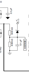
i use drv8302
i can't understood that topology below figure.because i did some simulation but still i didnt understand
what does this topology do , what is its job ,i added the ss,
please could you help me
best regards