This thread has been locked.

If you have a related question, please click the "Ask a related question" button in the top right corner. The newly created question will be automatically linked to this question.

DRV2624EVM-CT: Calibration fails for G1040

Part Number: DRV2624EVM-CT

Hi,

This is related to a previous post about not being able to make a haptic actuator pass the calibration and diagnostic routine, the part number is G1040003D, you can find the datasheet in here. After running the calibration the DIAG_RESULT bit is not set.

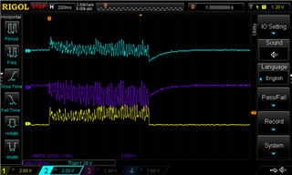
Find below multiple screenshots with the actuator configuration I'm using and the oscilloscope capture of the output signals,OUT+ (Channel 2 - blue), OUT- (Channel 1 - yellow) and OUT+ - OUT- (purple), signals.
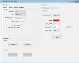
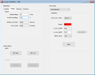
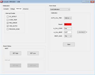
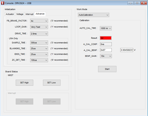
Output signals

From the look of the output signals can we assume the actuator is not being properly driven? Most likely a configuration option is not setup correctly?

  • Hello, 

    I would start by adjusting the LOOP_GAIN. Sometimes having it set too fast can make the driving waveform unstable and not allow the frequency to lock. If that doesn't work, I would try adjusting the LRA Only section. More information on each setting can be found in the register map or the datasheet. 

    Best Regards, 

    Justin Beigel

  • Hello, 

    Are you still having issues with this? Did changing the LOOP_GAIN help with this actuator? 

    Best Regards, 

    Justin Beigel

  • Hi,

    I haven't tried just yet, I had to work on something else. I will add another reply after trying setting the LOOP_GAIN.

    Regards,

    Carlos

  • Hello, 

    Sounds good. Looking forward to your response. 

    Best Regards, 

    Justin Beigel

  • Hi Justin,

    We were able to make the actuator pass most of the times the autocalibration and diagnostic routines, we had to modify the SAMPLE_TIME and BLANKING_TIME.

    Then we measured the acceleration using the acceleration measurement tool on the dev kit and our hardware, the dev kit was initially powered via USB and we got ~1.7G when driving the actuator on RTP mode at max value (the differential signal amplitude is 3.3V), then we used our hardware with the actuators powered with 3.3V, RTP mode and max value and we got ~1.2G (the differential signal amplitude is 2.5V).

    Then we powered the dev kit externally with 3.3V and got the same ~1.2G (the differential signal amplitude is 3.3V).

    On both cases RATED_VOLTAGE is ~2.4V and overdrive 3.3V. Do you happen to know if RTP mode works with VDD voltage instead of the programmed voltages?

    Regards,

    Carlos

  • Hello, 

    I need to double check on something with my colleague for this question but I will have an answer for you in the next day or two. 

    Best Regards, 

    Justin Beigel

  • Hello Carlos, 

    The RATED_VOLTAGE is an RMS voltage so the peak voltage of the waveform would be higher. If the output were a perfect sine wave, a 2.4Vrms would have roughly a 3.4V peak voltage. You can more accurately calculate the peak voltage using an equation in the datasheet if you desire but since the output is more square, the peak voltage should be just slightly higher than 3.4V.  You mention a differential amplitude, but what is the peak voltage in each case? I would suspect that the peak voltage for the case with the USB supply is higher than the output peak voltage for the 3.3V cases. The overdrive voltage acts like a clamp and can be limiting the peak driving voltage in both cases so you might get a similar peak voltage with the 3.3V cases being just slightly smaller. 

    If this is the case, it would be best to increase the overdrive voltage to a slightly higher value and use a 5V supply to drive the actuator as much as possible. 

    Best Regards, 

    Justin Beigel

  • Hi Carlos, 

    I haven't seen any activity on this thread recently so I am going to close it for now. If you have any further questions, feel free to post them here or start a new thread. 

    Best Regards, 

    Justin Beigel