This thread has been locked.

If you have a related question, please click the "Ask a related question" button in the top right corner. The newly created question will be automatically linked to this question.

DRV8889-Q1: DRV8889 issue

Part Number: DRV8889-Q1

Hi Team,

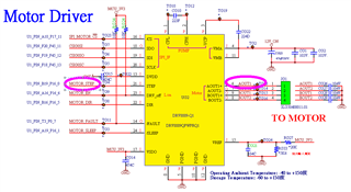
Customer use the following parameters here, and a continuous and complete PWM waveform can be measured at AOUT1 of the EVM.

But under the same conditions, I have measured incomplete waveforms on our PCB (please see the picture below). What conditions can cause this phenomenon

Motor parameter:

Full Step

Frequence:600Hz

PPS:300

Torque_DAC:5% / 41mA

 Winding resistance : 215ohm +-7%/phase
  • Hi Kygo,

    1. I would check if motor is connected properly ie. if wires of phases A and B are not mixed.

    If they are connected properly you can try the following steps.

    2. Can you verify that voltage at VREF is around 0.72V (divider works properly)

    3. Can you share Register values? The best way to be sure is to read them back.

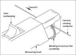
    4. It would be good to measure motor current as well but some low current probe would be needed and/or

    use a few turns to increase its sensitivity, if you have only 2-ch scope, please make current+voltage and current+steps measurements.

    Source: www.tmatlantic.com/.../index.php

    5. I would try to increase TORQUE_DAC and VREF and watch for changes in output waveforms.

    If motor nominal voltage is 12V or more you can safely run it with driver settings for higher currents.

    Regards,

    Grzegorz

  • Kygo,

    On the customer's board, each output has 0.1uF capacitor which may cause the OCP triggering if the output current is higher than 2.4A after 3us charging time.

    Also, if the switching frequency is 50kHz with 12V input, the power dissipation is 4x50kHz x (1/2) x CV^2=100k x 0.1u x 144 = 1.44W。It is too high. 

    Can you ask them to change that capacitor to 3.3nF or remove it first? And then, re-try it.

    Regards,

    Wang