This thread has been locked.

If you have a related question, please click the "Ask a related question" button in the top right corner. The newly created question will be automatically linked to this question.

DRV8302: drv8302 fault pins.

Part Number: DRV8302

hello expert;

i have a problem .

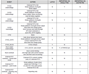
1-can you explain this table.could you explain with a example.

2-what output does pin give . i combine all gnd 

3-i drew the pin to wemos wifi module .

4-how do i read the faults with wemos .if i know the output ,i read easly .

because of i want to monitor the faults ,i use wemos which is wifi module.

thank you expert 

have a nize day

  • Hello,

    Thank you for your post! The table describes different fault events that may occur (such as n undervoltage  event on PVDD), as well as the action that the driver takes to protect the device in the case of a particular fault. In the case of an undervoltage event on PVDD, the driver will apply a weak pulldown on all the gates of the FETs and shut off all the external MOSFETs (this is also known as HiZ). This is done to protect the DRV during this fault.

    Another thing this table explains is whether or not the fault is latched. In the case of the PVDD undervoltage event, this type of fault is not latched so once the condition for the fault no longer exists (PVDD rises above the undervoltage lockout threshold), then the DRV will resume operation. If the fault is a latched fault, it will not resume operation even after the condition for the fault is no longer present. it is necessary to apply a reset pulse on the EN_GATE pin in order to resume operation for a latched fault. More information on how to clear a latched fault can be found in the "Action" section of the table as well as in the datasheet.

    The final 2 columns of the table discuss the reporting method that the DRV uses to report the fault. There are 2 pins on the device that are used for Fault reporting: the nFault pin and the nOCTW pin. These pins are both open drain pins, so they need an external pullup resistor to operate properly. When a fault occurs and is reported on one of these pins, that pin is pulled low to indicate a fault. The table indicates whether or not nOCTW pin or the nFault pin will be pulled low to report a fault. 

    The nOCTW and the nFault pins can be routed to the MCU as inputs to the MCU. The MCU would then have to read the voltage on that pin to detect if the pin is high or low, and could then tell when a fault has occurred when it detects that one or both of the pins are pulled low. These pins can help notify the MCU when a fault has occurred, but the specifics of what caused the fault cannot be exactly determined by these pins. This is because as you can see in the table, the nFault and nOCTW pins can be pulled low for different types of faults (for instance, the nOCTW pin is pulled low when there is an over temperature warning, but also is pulled low when there is an overcurrent event (in this table it is called External FET Overload instead of overcurrent event) for one of the MOSFETs). 

    For more information on the various faults and protection features, you can refer to section 7.3.4 of the datasheet.

    Regards,

    Anthony Lodi