Hi,
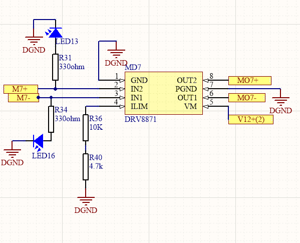
We are using the DRV8871 as a motor driver for a small motor (R=10 Ohms). Its nominal current is well within 300mA.
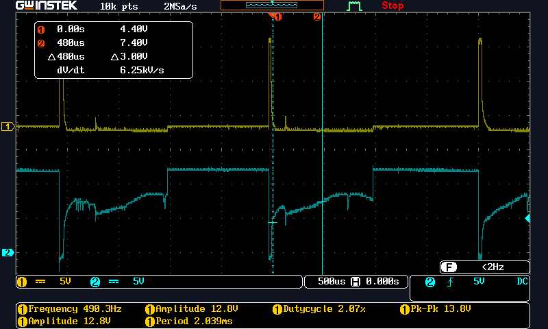
The problem seems to be that when we are changing the duty cycle, the output somehow shows a distorted voltage. We verified with a couple of chips and they all show the same issue.
The inputs are as follows:
VM=12.3V , PWM Duty cycle = 50% , IN(X) Voltage = 3.3V , PWM Frequncy = 500Hz.
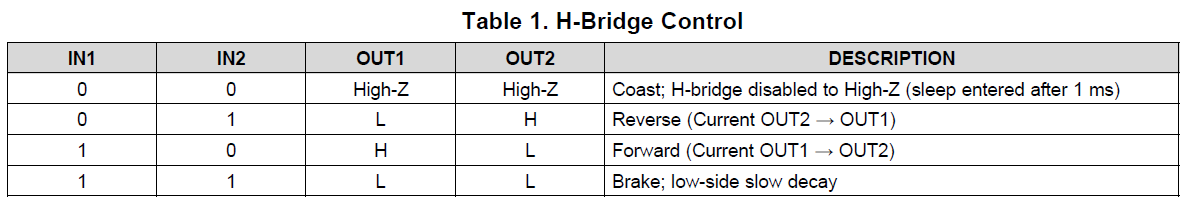
IN2 is shorted to GND and we have more than adequate decoupling using 5 100uF Capacitors.
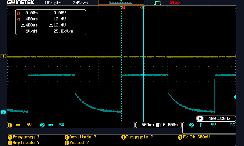
Below is an oscilloscope shot with the motor connected and running at no load condition: CH1:- DRV8871 Output to the ground (OUT1), CH2:- DRV8871 Input (IN1).

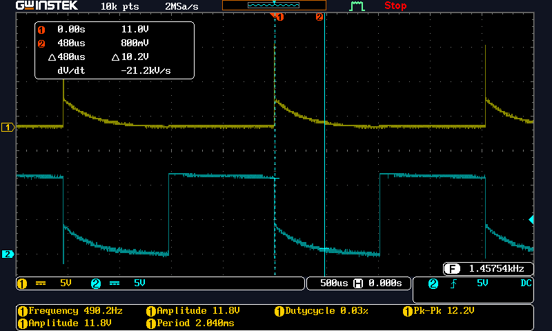
Below is an oscilloscope shot with the motor connected and running at no load condition : CH1:- (OUT2-GND ), CH2:- (OUT1- GND).
Below is an oscilloscope shot of the output with nothing connected : CH1:- (OUT2-GND ), CH2:- (OUT1- GND).
Below is an oscilloscope shot of the output with a 33Ohm Resistor Alone : CH1:- (OUT2-GND ), CH2:- (OUT1- GND).
Can you help me out? I can't understand why the output is not able to follow the input square wave even at no load.
Regards,
Tony