This thread has been locked.

If you have a related question, please click the "Ask a related question" button in the top right corner. The newly created question will be automatically linked to this question.

DRV8353R: Motor chattering issue when motor RPM > 90% of max motor RPM

Part Number: DRV8353R
Other Parts Discussed in Thread: DRV8353, MOTORWARE, OPA835, DRV8343-Q1

We are working on debugging the first revision of our own custom hardware. We have largely copied the DRV8353RS-EVM (same values for current filter, voltage sense filter, VCP cap, CPH/CPL caps). We are seeing an issue where when the motor RPM gets to around 90% of the Max motor RPM for a given voltage (happens at any voltage from 24V-45V VM), we start to get chattering in the motor and start to lose control. If I increase the voltage on the power supply a few volts, the chattering goes away. The FET gates all look good up to and beyond this point. The charge pump voltage also looks good.

Layout is done on a 6 layers with nearly all feedback signals running perpendicular to high current paths and generally sandwiched between stitched ground layers. DRV8353 layout was copied a directly as possible from EVM. This occurs on an unloaded motor and at low currents. I am curious if anyone else has seen this type of issue or has any ideas for next steps in terms of troubleshooting.


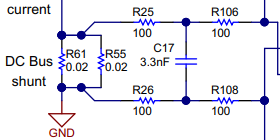
Rshunt =  2x 3mOhm in parallel (1.5 mOhm) @ 20 gain (USER_ADC_FULL_SCALE_CURRENT_A=110A)
FETs = 2x IAUT300N10S5N015ATMA1 (330 nC total Qg with 2 in parallel)
Idrive (HS/LS) Source = 1000mA
Idrive (HS/LS) Sink = 1800mA

USER_PWM_FREQ_kHz = 20 kHz
USER_NUM_PWM_TICKS_PER_ISR_TICK = 1
USER_NUM_CTRL_TICKS_PER_SPEED_TICK = 20
USER_NUM_CTRL_TICKS_PER_TRAJ_TICK = 20


Motor L = 280 uH
Motor R = 0.2 mOhm
Motor Pole = 3 pole pair

  • Here are some scope shots of some duty cycle anomalies (signal is Vgs on a high side gate) we think are coinciding with the motor chattering / loss of control. I would expect the duty cycle to slowly ramp up and down in a sinusoidal fashion. In the shots below, it appears the duty cycle is changing rapidly and then returning to a more expected range.


  • Hello Drew,

    Thanks for posting on the E2E forums. Let me see if I can give you an answer tomorrow, 12/17/20.

    Best,

    -Cole 

  • Hello Drew,

    You're using C2k, Instaspin FOC right? Essentially, I'm trying to figure out if you own the control (or the INx signals). Assuming, the INx match the VGS signals you've posted, then this means the algorithm is deciding to lower the speed on the device. This wouldn't be a DRV835x problem and we can jump into the algorithm in more detail. It almost sounds like some sort of current limit if the decrease is intentional but it might be a sensing issue if it is not.

    If the INx does not match the VGS, then this is a DRV835x problem where the signals are not being translated correctly, which is a problem I've never seen in context of the DRV835x

    Best,

    -Cole

  • Cole,

    Yes, we are actually using the same top driver board that comes with the DRV8353RS-EVM. We are also using the DRV8353Rx GUI with some every so slight modifications to the project_5b motorware firmware. If we run the same firmware on the actual DRV8353RS-EVM replacing the stock 7 mOhm shunt resistors with1.5 mOhm ones, we don't see this problem. Seems to be something related to our custom hardware that is causing the problem. I can maybe try cross posting this over in the Instaspin forum as well. 

    Cross post in C2000 forum

  • Hello Drew,

    Thanks for verifying. 

    I'm not super familiar with how they implemented the algorithm but I'm pretty sure their software project needs information about the hardware to scale the output from the DRV8353's current sense amplifier (which is the backbone FOC).

    Either way, I think this is better handled by the C2k team as its pretty clear that the control is making the decision to change the INx (and subsequently the GHx and GLx) behavior. 

    As such, I'll close this thread, let the C2k folks know that you posted here, and let them loop me in again on the other thread you've made if necessary..

    Thanks,

    -Cole

  • Cole,

    Cross post in C2000 forum

    I've worked now for quite some time with the C2k team. At this point in time, we've narrowed the problem down to where the motor control works fine in a torque control mode, provided the USER_MAX_VS_MAG_PU stays below 0.57 (100% duty cycle) for the PWMs. Whenever we attempt to go into overmodulation > 0.57, we immediately see a GDF fault trip, and about 90% of the time it causes permanent damage to the DRV8353. I'm growing more concerned that this issue isn't related to the voltage or current feedback signals. We've looked into these quite extensively and gone so far as using an extra PWM channel to output the raw values in the ADCs for voltage and current and the waveforms all look quite good.

    Is there something in the performance of the DRV8353 part that would cause a failure when the "on" time of a particular high side FET exceeds some threshold. When the overmodulation goes above 0.57 there starts to be consecutive PWM periods of 100% duty cycle. Below that amount, there is always some amount of time spend in the off state.

    Below is a link to the data sheet of the FETs we are using (x2 in parallel):

    www.infineon.com/.../Infineon-IAUT300N10S5N015-DS-v01_00-EN.pdf

    Regards,

  • Hello Drew,

    Here's my assumptions, feel free to correct anything because there's a lot of info to catch up on.

    • You've used the same algorithm with the EVM and no issue in overmodulating
    • You're "custom" board changed the FETs and made them in parallel, which by extension, changes the layout
    • Problems don't arise until overmodulation goes higher than 100%, which is expected to push current higher (and speed)
    • The symptom is gate drive fault and the DRV is damaged and can be replaced to "fix" a board
    • There's no consistent phase, pin, or leg that gets damaged, its spread between all 3

    Based on these assumptions, this sounds like the overmodulation is resulting in some bigger voltage spikes as a result of parasitics in the layout and design. The gate drive fault would then be the symptom as the spikes would cause gates to short to a source, within the device, which would not allow the gate of the FET to turn on after it is shorted.

    You could either try and measure the waveforms of gate and source for high side and low side to confirm this might be the cause. Otherwise, you can try these methods to see if the issue goes away, which is a bit experimental in nature.

    • Cut up some trace and add small (3-7 ohm) gate resistors in front of each the parallel FET (if you haven't already)
      • The mismatched LC from layout and FET gate capacitance can causes ringing between the two gates of the parallel FETs as current flows from the Gxx pin to charge the gates of the FETs and then the charge bounces between the two gates
    • Lower gate drive current lower and see if more margin till damage is increased
      • The theory says you shouldn't be higher than 600mA, if you didn't change the default gate drive current from the EVM. Definitely lower it if you are above that.

    • Try adding a 100nF to 1uF capacitor between SPx and VDRAIN to reduce negative spiking

    Let me know if any of this helps.

    Best,

    -Cole

  • Cole,

    Your assumptions are all correct except the following clarifications:

    • We have now removed the second FET in parallel to try and simplify things.
    • We also went up from 1.5 mOhm shunts to 7 mOhm shunts to try and better match the EVM specs.
    • We currently are using 600mA sink / 300ma source current for the DRV.
    • We generally see no damage to the FETs at all, only damage to the DRV parts in the form of a GDF fault that will not clear and if disabled, the part does not output the right gate drive signals.

    Is the negative spiking you are talking about what we are seeing below? This waveform as taken with the run identify on but the motor not yet spinning. We see a spike on the current feedback signals at each PWM pulse even when the motor isn't spinning. When you say VDRAIN, do you mean the battery / power supply voltage? I believe that is what you call VDRAIN your EVM schematic, or do you mean connect to the drain of the low side FET, aka the phase voltage output?

    Right now with a single FET, we have 0 ohms put in as the gate resistor like the EVM. Would it help to increase those values to help soften the gate drive? In a traditional design, we would do this but my understanding was that the DRV was responsible for limiting the current into and out of the gate. You also mention "mismatched LC from layout and FET gate capacitance". Should we be targeting specific trace inductance and capacitance numbers to match the FETs we have selected?

  • Hello Drew,

    We have now removed the second FET in parallel to try and simplify things.

    Understood, if you can cut the trace leading to the 2nd FET, to reduce any impedance mismatch as a result of the stub, it would help decrease any parasitic effects.

    Is the negative spiking you are talking about what we are seeing below? 

    The negative spiking usually happens when a PWM gate signal transitions from high to low, causing the phase node to do the same, so the signal is supposed to be GND and the negative spiking goes below GND to violate the negative absolute maximum spec for the gate or source (or differential gate - source) specification.

    So, this waveform isn't applicable. But it does look noisy, might be a clue to the state of your layout or something else.

    When you say VDRAIN, do you mean the battery / power supply voltage? I believe that is what you call VDRAIN your EVM schematic, or do you mean connect to the drain of the low side FET, aka the phase voltage output?

    Sorry, I meant the high side FET's drain (which should have traces running to the VDRAIN of the DRV and is the same node as the battery supply, usually) to low side FET drain source (above the sense resistor or at the FET where traces will run to the SPx pin). I'm just trying to emphasize the location of where the cap is connected.

    DRV was responsible for limiting the current into and out of the gate

    Yes, this is the purpose of IDRIVE and gate resistors, in general, do the same thing.

    In the parallel case, the first MOSFET turns on and it will cause a rapid voltage swing at the source node as it starts to conduct. This voltage can couple through the parasitic gate-drain capacitance of the other MOSFET, and cause a voltage spike on the shared gate connection. This can cause oscillation on the gate line as the MOSFETs rapidly turn on and off, and ultimately damage the gate driver or MOSFETs. This is why the series resistors in the parallel MOSFETs are important. While the charge goes into the gate of the first FET turning on, ultimately, the charge jumps back and forth between the gates, which the DRV cannot control.

    Should we be targeting specific trace inductance and capacitance numbers to match the FETs we have selected?

    Not really, just the best you can. Here's an app note on what we define as good layout: 


    Best,

    -Cole

    Edit: corrected capacitor location

  • Cole,

    That good news is that once I put a 10 (smallest I had on hand) ohm gate resistors on our FET, I'm not longer getting a GDF fault and taking out the DRV part with a PU above 0.5. I can now run up to 0.666 pu without issue. In an effort to make debugging easier, our current revision has the components fairly spread out and I think this is making for less than ideal paths from the DRV to the FETs and other sense lines. I have some lower values on order so we will see what happens when I take that value down to 3-5 Ohms.

    Your suggestion of adding a capacitor between SPx and VDRAIN (aka battery voltage) also helped decrease the negative spike on the shunt. It is still there and I think I plan to put some pi filtering on our next revision to try and see if we can filter this a little more (diagram below). I'm still a little concerned this spike could be introducing some noise when the duty cycle increases and the measurement window decreases. You can see below on the screen capture what I'm talking about. I do see a similar spike on the EVM, so I'm not certain how much of this spike can be eliminated. The guide below does show some graphs using an OPA835 as the current shunt amplified that has the spike completely eliminated. That part does have a much higher slew rate and much better bandwidth than the ones integrated into the DRV.

    www.ti.com/.../tiducy7.pdf

    As before, thanks for the additional feedback and troubleshooting ideas. I think we are back on a good track here. I think we still have a few improvements to make, but I'm hoping that we can start to test things a slightly higher power levels now.

  • Hello Drew,

    Glad to hear things are working out in the right direction.

    As for the filter, there's some real concern about putting resistance in the SPx path. If you look at figure 32, the gate driver block diagram, the SPx pin acts as the return path for the current that's stored in the gate that gets discharged (or sunk) into the source pin which happens when the low side turns off. Something like the DRV8343-Q1 has dedicated pins separated from the sensing lines which wouldn't have that interaction.

    That doesn't guarantee that it won't work, we just need to be careful that adding the footprints and having the low side gate drive sink current travel through the resistor doesn't introduce any other ringing into the system. So, just needs some testing, even better if you can hack up the board you have now and test it, provided there's space.

    If it does work, as long as you ensure those resistors are <1k ohm then there shouldn't be too much contribution to the gain or gain error as a result of mismatch between the two. You essentially only need R25, R26, and C17 as the R106 and R108 equivalents are already inside the device (as they only contribute to the gain, not the input filtering).

    Keep us posted on the developments, I'm going to mark your most recent post for now.

    Thanks,

    -Cole

  • Cole,

    Thanks for calling my attention to that portion of the block diagram. Is it possible those large spikes at the start of current conducting thru the shunt (positive spike) as well as the end of the conductions (negative spike) could be attributed to dual use of the SPx pin as the return path for the low side gate? Our SPx and SNx traces on the board are fairly long and not super wide. They are well shielded from high current planes and other noise, but we were not aware the SPx line would be carrying potentially amps worth of current. Could the length/width and therefore resistance of the SPx trace be cause of these spikes?


  • Hello Drew,

    I see, yes it could definitely be contributing. I believe there is some text in the datasheet about keeping Gate and Source lines matched in length, width, and others. It also means the SNx should be thicker, by extension, as the sense inputs should also be "matched" to prevent differential noise. 

    Best,

    -Cole

  • Cole,

    I wanted to let you know, we are now able to get to full 0.666 overmodulation even with our existing hardware. I had to increase the svgencurrent minimum width to 3 us for the default of 2 us. I think that spike on the current waveform from the low side gate return current requires a minimum settling time of closer to 3 us and thus we need to engage current reconstruction earlier than normal.

    One other problem I'm now struggling with is if I try to change the default 20V/V gain on the DRV8353 in drv8353.c, to anything else, it doesn't appear to be setting it correctly over the SPI. For instance, if I don't update the user.h parameters and I were to change the gain from 20 to 10, I would expect to measure roughly double the IQ current on the motor phase or half it I set it to 40. Please see the code I'm using below to attempt to set this:

    void DRV8353_writeData(DRV8353_Handle handle, DRV_SPI_8353_Vars_t *Spi_8353_Vars)
    {
      DRV8353_Address_e drvRegAddr = 0;
      uint16_t drvDataNew = 0;
    
      Spi_8353_Vars->Ctrl_Reg_03.IDRIVEN_HS = ISink_HS_0p900_A;
      Spi_8353_Vars->Ctrl_Reg_03.IDRIVEP_HS = ISour_HS_0p900_A;
      Spi_8353_Vars->Ctrl_Reg_04.IDRIVEN_LS = ISink_LS_0p900_A;
      Spi_8353_Vars->Ctrl_Reg_04.IDRIVEP_LS = ISour_LS_0p900_A;
      Spi_8353_Vars->Ctrl_Reg_05.DEAD_TIME = DeadTime_100_ns;
      Spi_8353_Vars->Ctrl_Reg_05.OCP_MODE = Latched_Shutdown;
      Spi_8353_Vars->Ctrl_Reg_05.VDS_LVL = VDS_Level_0p060_V;
      Spi_8353_Vars->Ctrl_Reg_06.SEN_LVL = SEN_Lvl_Ocp_0p25;
      Spi_8353_Vars->Ctrl_Reg_06.CSA_GAIN = Gain_10VpV;

  • Hello Drew,

    To my knowledge, there's no dependency for any of the registers for CSA_GAIN. And you've verified that your SPI communication protocol has been able to successfully change registers? You've been able to write and the read back the changed values?

    Assuming that is all taken care of, I'd like to verify that the CSA is working as expected. Remove the motor and apply a know voltage the SPx and SNx and see if the output voltage follows the equation in the datasheet. The DC check should be relatively easy. Then change the gain and try again.

    Best,

    -Cole

  • Cole,

    I appears to maybe be a bug in the SPI firmware driver in motorware right now. If I command the driver to write the SPI values a second time, the CSA_GAIN seems to take. If I just let the driver run normally without sending the value a second time, it just stays at the default 20V/V gain.

    Regards,

  • Cole,

    I appears to maybe be a bug in the SPI firmware driver in motorware right now. If I command the driver to write the SPI values a second time, the CSA_GAIN seems to take. If I just let the driver run normally without sending the value a second time, it just stays at the default 20V/V gain. For now, it seems we've got a workaround.

  • Hey Drew,

    Sounds good to me. Glad there's a workaround, was going to push the thread back to C2k as they own motorware. I'll notify them that this is a thing that's happening.

    For now, I'll like to close this thread and if you have another follow up question then I'd rather use the "ask related question" so we have the history but don't need to look through all of these replies to get the status or question of where we are at. Does that make sense?

    Best,

    -Cole

  • Cole,

    Sounds good to me. I'll start a new thread if I run into further problems. I agree that we won't want to make things too long. We've tested power up to 2 kW today on the power stage so we are up and running.