A related question is a question created from another question. When the related question is created, it will be automatically linked to the original question.
If you have a related question, please click the "Ask a related question" button in the top right corner. The newly created question will be automatically linked to this question.
TPS2546: Load detection - Power wake: set/reset time
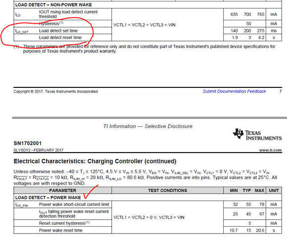
In both of the tables you shared, you will see that the center column says Test Conditions. The test conditions outline the configuration the TPS2546 must be in, which is determined by the voltage applied to the CTL pins. The load detect for Power wake is less than non-power wake, as the power wake functionality is intended to be used to wake the system and inform the system that a device has been connected. Non-power wake would be used in a S0 power state
The power wake reset time is the amount of time it take for the STATUS pin to go back HI, indicating that there is no longer a load attached to that port
The purpose of the load detection circuit is to indicate to the system when a load has been attached which would pull a constant current. This is just an in rush current spike which is not enough to indicate that a load has been detected.
We do not have the timing for load detection set time -power wake is not available
Unfortunately no. I have previous commitments that I need to work on beforehand. If the customer needs it beforehand, then they can actually conduct the test themselves. Just connect a light load on the VBUS pin, and see at what point the STATUS pin goes low.
Adam is out of office currently, he should be able to get back to you next week. Could you please have customer test on their board as Adam described in the meantime, it should be too difficult to do the testing?
I also would like to measure the parameter by myself but our country recently outbreak COVID-19. Therefore, we could not visit our customer to debug and should stay home to work.
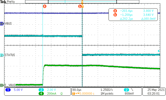
Thank your help. Actually, I would like to know the detection time not STATUS transform. How long will I_VBUS trigger the STATUS as I_VBUS over the threshold?
You could refer the above waveforms from customer that descript the duration over the threshold and cause STATUS to change its state.
I am not sure I understand your question. It will take about 200us of I_VBUS over the threshold before the STATUS pin is asserted. The STATUS pin will remain asserted for as long as the current on VBUS is above the threshold.
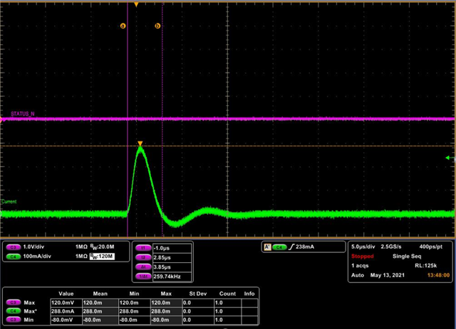
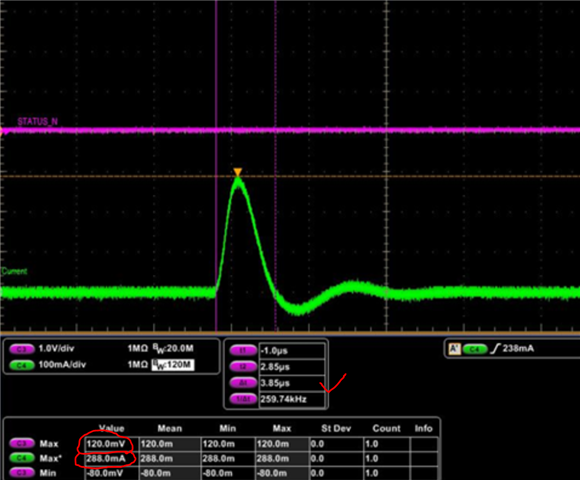
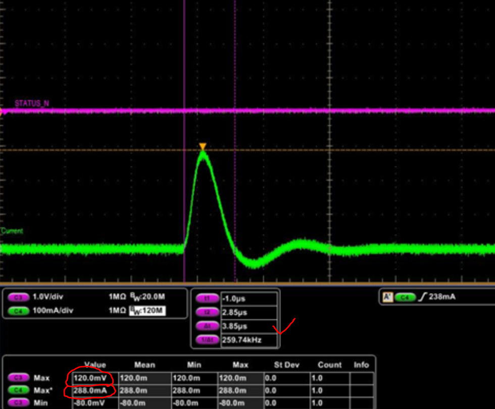
If your measurement is that I_VBUS should take 200us over the threshold before the STATUS pin changing. However, the below picture seems not matching your result. There is a periodical current spike which over threshold but less than the 200us why is the STATUS pin asserted?
Geen: I_VBUS; Purple: STATUS; 3.85us over the threshold; I_VBUS Max: 288mA, STATUS: 0V
I would like to know what is the minimum duration of I_VBUS over threshold causing STATUS pin changing??
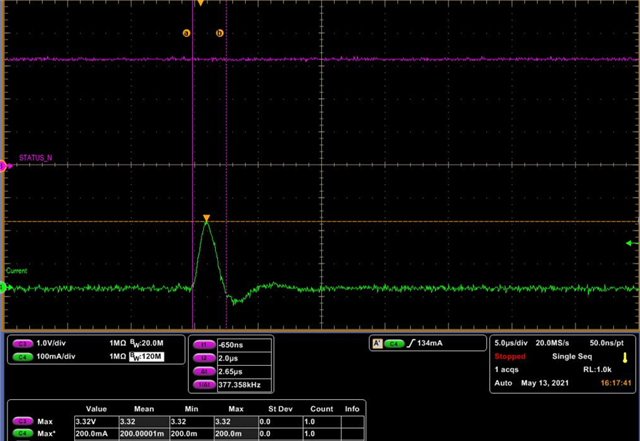
In your waveform, the I_VBUS is near constant value but my customer met the problem is current surge.
You can see that the STATUS pin is already low when the current spike is seen. So something is occurring before the current spike in this measurement. The current spike shown in the measurement is not causing the STATUS pin to go low
In your waveform, the I_VBUS is near constant value but my customer met the problem is current surge.
Is this current surge being seen when no adapter is connected? If so, then that is the problem. Why are their transient current spikes without any device connected. If this current surge is from a connected device, then wouldn't the system want to know that a device has been connected?
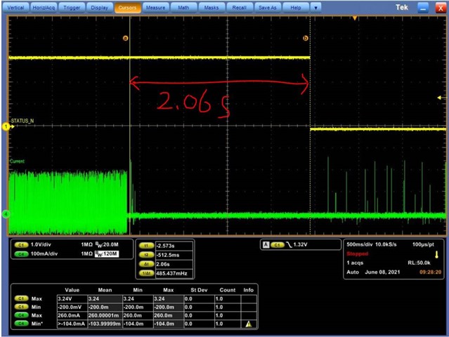
You can see in the electrical characteristics for the power wake mode, that it has a typical reset time of 15 seconds. So the STATUS pin could eventually be going back High, but it does not show in your capture.