Hi expert,
This device has SYNC pin and has options for SYNC mode: CLF Mode(Int CLK) and PLL Mode(ext CLK). It can be configured through E4h.
My questions:
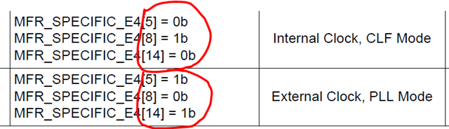
1. Why do these discerptions below from two places(DS, TRM) look different? In DS, it looks that only one of these two modes can be realized.
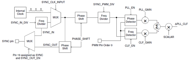
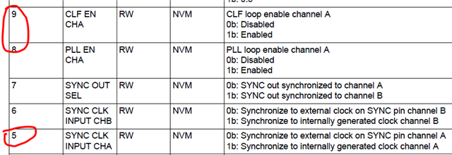
But in TRM, these two enable signals are independent. Can CLF loop and PLL loop operate at the same time? Also, the E4h[14] looks no relationship with mode enabled.
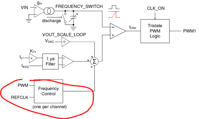
2. It looks too me that CLF loop is a slow closed-loop frequency-loop to adjust on-time, to ensure fsw close to the target fsw we set, especially when load current is high.
However, frequency control is claimed one per channel, e.g. channel A is configured with 12 ph in total. Does it mean phase 1- phase 12 will share the same frequency control output of Δton, along with PWM order 0 only?
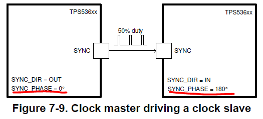
3. PLL loop is for phase tracking with specific CLK only, that means we can use two TPS536C7 to realize 24ph interleaving, right?