Other Parts Discussed in Thread: CSD17507Q5A, CSD86336Q3D, CSD86350Q5D, CSD87351Q5D
Hi,
We are planning to use TPS53015 part in our board. Our system requirements are listed below.
1. 19V input (+/-5%), 3.3V Output
Output Current : 7A
Operating Temperature : 0C to 50C
2. 19V input (+/-5%), 5V Output
Output Current : 6.5A
Operating Temperature : 0C to 50C
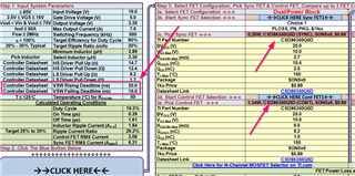
The application design in TPS53015 datasheet uses discrete FET CSD17507Q5A parts. With the help of TI's FET loss calculation sheet, We were able to calculate the FET losses to determine the maximum ambient temperature with & without external gate resistor(for HS FET only). We have tabulated the values in the attached sheet (refer "FET Loss (Discrete)" sheet). We have also considered half bridge FET parts (CSD86336Q3D,CSD86350Q5D) based on the FET loss calculation sheet and tabulated the loss and max ambient temperature values in the sheet (refer "FET Loss (Dual)" sheet).
Based on the CSD17507Q5A datasheet, the Rja values are dependent on copper area connecting the DRAIN pad. Datasheet suggest that for minimum DRAIN pad area, Rja would be 125C/W. Although, it may be possible to have greater copper area for VIN trace connecting the DRAIN of the control FET, the copper area connecting the DRAIN of sync FET needs to be minimal as per our understanding as its SW node.
Q1) Under this condition, We wont be able to meet our product's ambient temperature requirement of 50C. Could you please let us know is there a way to overcome this to use discrete FET?
The dual FET parts identified from FET loss sheet appears to have PGND pad which can be used connected to GND for heat to escape from FET. Our design would have atleast 2 GND planes and we think this should help lower the Rja value.
Q2) Could you please let us know if its fine for us to use any one of the suggested dual FET part with TPS53015 (0C to 50C) ?
The FET loss value has increased atleast by ~0.3W with inclusion of 10Ohm gate resistor to HS FET. The application design includes that same only HS FET not for LS FET. The additional loss brings down the calculated max ambient temperature closer to 50C. (Note: 10 ohms was added on top of the max HS Driver pull up/pull down values of TPS53015 to calculate loss)
Q3) Is it fine to replace the gate resistor with zero ohms? Also, Do we need include one for gate of the LS FET as well?
We have also attached TI's FET sheet which we had used for loss computation. Let us know if you find anything off with the values.
We will look forward for your reply at the earliest as we are in the middle of the design.
Thanks,
Balaji


