This thread has been locked.

If you have a related question, please click the "Ask a related question" button in the top right corner. The newly created question will be automatically linked to this question.

TPS6594-Q1: buck converter abnormal behaviors root cause

Part Number: TPS6594-Q1

hello

there are abnormal behaviors at TPS6594121 buck SW node on my board.

could you please help me to find the root cause?

my NVM settings are ( buck1/2/3 Multi Phase , FPWM enable , Spread Spectrum enable , Switching freq = 2.2M , Vin = 3.3V , Vout = 0.8V , 470nH , 47uFx2 on per phase , 47uF on Load / every values are recommanded)


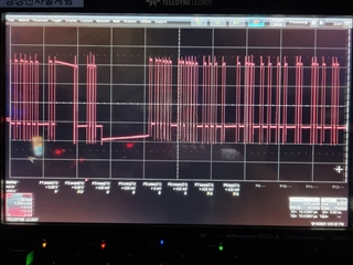
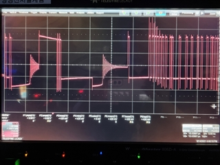
there are three abnormal behaviors in below waveforms.

1. Delayed switch HIGH to LOW (left picture)

2. Delayed switch LOW to HIGH (left picture)

3. looks PWM to PFM transition, even if setting FPWM. (right picture)

could you please give me ideas to make almost square switching waveform?

  • Hello, Mr. Kim,

      When operating in PWM mode the phases of a multi-phase regulator are automatically added or shed based on the load current level. You can try to set the BUCK1_FPWM_MP=1 to force buck1/2/3 in multi-phase mode to make almost square switching waveform.

    Thanks!

    Phil

  • Thank you for your reply and recommendation.

    i want to know below the features in that switching voltage waveform(buck1/2/3 Multiphase)


    1. Delayed switch HIGH to LOW / LOW to HIGH 

     -> i saw the slow switching freq (600Khz~ ) 

     -> operated transition from PWM to PFM

     -> operated phase shedding

    2. faster than already setting frequency(2.2Mhz)

     ->  i saw the fast switching freq (~5Mhz )

     ->  operated phase adding


    Q1) is it right? and is it normal behavior? the reason why i ask you is that there are no Electrical Characteristics Data in the datasheet regarding this. So, I don't know that it is normal or abnormal.


    Q2) In the photo, there is a point where it stops at the lowest point(maybe starting from undershoot) and then starts switching.
    and also there is a point where it stops at the middle point(maybe starting from zero) and then starts switching. 

    can you explain what the differences are? and is it normal behavior?


    3. DCM (in the right-side of the picture)

    -> there are ringing wave in the middle of the switching voltage waveform.

    Q3) how can i disable DCM behavior? 


    Q4) i actually cannot distinguish between 'phase adding/shedding' and 'transition PWM to PFM'.  could you please explain differences? 


    best regards.

  • Hello,

        The waveforms that you have provided indicate that the regulator is operating in an unstable condition.  I do not think we will be able to provide a sufficient answer for questions 1 and 2 in this forum, however, the waveforms are understood and expected if the system is unstable.

        I am not familiar with any control mechanism for DCM, but will investigate.   

    For Q4, the PWM and PFM are discussed in section 10.3.2.1 Buck Regulators of the datasheet.

    "There are two modes of operation for the converter, depending on the output current required: pulse-width modulation (PWM) and pulse-frequency modulation (PFM). The converter operates in PWM mode at high load currents of approximately 600 mA or higher. Lighter output current loads cause the converter to automatically switch into PFM mode for reduced current consumption. The device avoids pulse skipping and allows easy filtering of the switch noise by external filter components when forced-PWM mode is selected (BUCKn_FPWM= 1). This is the recommended mode of operation for the buck converter to achieve better ripple and transient performance. The drawback of this mode is the higher quiescent current at low output current levels."

    Regards,

    Chris