This thread has been locked.

If you have a related question, please click the "Ask a related question" button in the top right corner. The newly created question will be automatically linked to this question.

LM2735: Comportamiento erroneo Vout LM2735

Part Number: LM2735

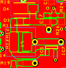
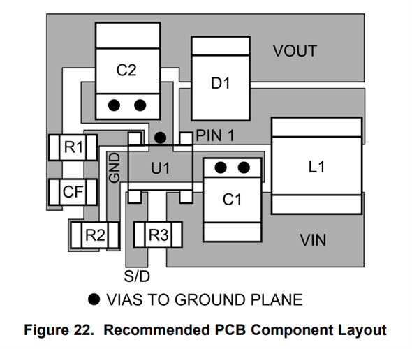
I am having problems with the LM2735 components.


The boost output is not getting the output I want, it is much higher. And I think they are burning out the component.
I need a 14V output, and I'm measuring voltages of 25-30V.


This circuit simply has to charge a 1500uF or 3000uF capacitor.
Then the boost is switched off, and once it has been switched off, the capacitor is discharged.

  • Hi Daniel,

    1. Have you doubled checked if the feedback resistors are correct? If feedback resistors are not correct, you would see a incorrect Vout.

    2. Did you follow TI recommended layout? The layout always makes an important role for a converter performance. 

    3. You need to place a low-ESR ceramic capacitor close to rectifying diode cathode and IC GND pin.

  • Hola,

    1. Yes, I have verified that they are correct and have tried different combinations. 

    R19(K) R21(K) Vout
    1020 100 14,056

    R19(K) R21(K) Vout
    100 10 13,805

    2.Yes, Minimum track width 1.3mm. 

    3.The closest capacitor is this EEV-FK1V152M. Is it also necessary to put one like this C3216X5R1E106M?

    Thanks

  • Hi Daniel,

    2. The layout still have some improvement room. Below picture shows TI recommended layout. For a boost converter, the most critical path is L1, SW node, rectifying diode, Cout, IC GND pin. These components, node should be placed very close to each other. The output capacitor should be very close to rectifying diode cathode and IC GND pin.

    The FB trace is extremely sensitive to noise and feedback network must be placed close to FB pin.

    3. Right. Please put a C3216X5R1E106M085AC close to diode cathode and IC gnd pin. 

    Please also share some key waveform, Vout, FB, SW on E2E. It may help debug.

  • Can we discard that the problem is not the coil model VLCF5020T-100M1R1-1 ?

  • Hi Daniel,

    You remind me that the inductor also needs to be replaced with a higher saturation level part. This VLCF5020T-100M1R1-1 Isat is 1.13A while the boost converter switch current limit is 3A typically.