We are using BQ25713 chip in our schematic. Schematic design is based on BQ25713 dev board schematic.
We are using 12-14V adapter and 3S Li Ion battery.
We are facing several issues.
Charging current and power consumption from adapter is OK if we do not draw more than 6 A from VSYS.
The problem occurs when load on VSYS draw more than 6A current (approximately) for around 10s. Then Input current drops to around 3A and remaining current is drawing from the battery.
If VSYS is disconnect, battery charging current is also dropped to 0.4A. If I connect the same load (peak above 6A) in that state, input current is limited to around 3A and remaining current is drawing from the battery again.
Adapter can give up to 10A.
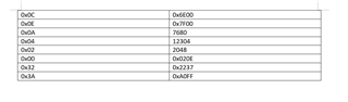
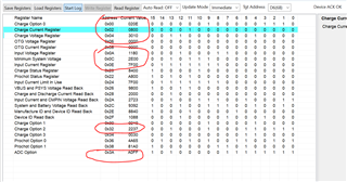
My initial BQ25716 configuration (after POR):
void Configure_BQ25713_ON (void)
{
//configure BQ25713
I2C_reg_addr = 0x0C; //MinSysVoltage (two register) 0x0D - 0x0C
I2C_data_full = 0x6E00; //11776 mV
I2C_data[0] = (I2C_data_full & 0xFF); // Reg data LSB
I2C_data[1] = ((I2C_data_full >> 8) & 0xFF); // Reg data MSB
i2cSend(I2C_ADDR_BQ25713, I2C_reg_addr, 2, &I2C_data[0]); //2 bytes lenght
//
I2C_reg_addr = 0x0E; //Input current limit (two registers) 0x0F - 0x0E
I2C_data_full = 0x7F00; //IIN_HOST = 6350 mA
I2C_data[0] = (I2C_data_full & 0xFF); // Reg data LSB
I2C_data[1] = ((I2C_data_full >> 8) & 0xFF); // Reg data MSB
i2cSend(I2C_ADDR_BQ25713, I2C_reg_addr, 2, &I2C_data[0]); //2 bytes lenght
//
//If the input voltage drops more than the InputVoltage register allows, the device enters DPM and reduces the charge current.
I2C_reg_addr = 0x0A; //Input voltage Limit (two registers) 0x0B - 0x0A
I2C_data_full = 10880 - 3200; //10880 mV -3200 mV offset
I2C_data[0] = (I2C_data_full & 0xFF); // Reg data LSB
I2C_data[1] = ((I2C_data_full >> 8) & 0xFF); // Reg data MSB
i2cSend(I2C_ADDR_BQ25713, I2C_reg_addr, 2, &I2C_data[0]); //2 bytes lenght
//
I2C_reg_addr = 0x04; //Charge voltage limit (two registers) 0x05 - 0x04
I2C_data_full = 12304; //12304 mV (For Li-Ion 3S2P pack, Charge voltage limit (two registers) 0x05 - 0x04 = 0x3010 (8 mV step))
I2C_data[0] = (I2C_data_full & 0xFF); // Reg data LSB
I2C_data[1] = ((I2C_data_full >> 8) & 0xFF); // Reg data MSB
i2cSend(I2C_ADDR_BQ25713, I2C_reg_addr, 2, &I2C_data[0]); //2 bytes lenght
//
I2C_reg_addr = 0x02; //Charge current limit (two registers) 0x03 - 0x02
I2C_data_full = 2048 ; //2048 mA
I2C_data[0] = (I2C_data_full & 0xFF); // Reg data LSB
I2C_data[1] = ((I2C_data_full >> 8) & 0xFF); // Reg data MSB
i2cSend(I2C_ADDR_BQ25713, I2C_reg_addr, 2, &I2C_data[0]); //2 bytes lenght
//
I2C_reg_addr = 0x00; //Charge option 0 (two registers) 0x01 - 0x00
I2C_data_full = 0x020E; //multiple settings: EN_LWPWR = 0, WDTMR_ADJ = Disable, IDPM_AUTO_DISABLE = 0, OTG_ON_CHROK = 0, EN_OOA = 0, PWM_FREQ = 800 kHz, LOW_PTM_RIPPLE = 0,
//SYS_SHORT_DISABLE = 0, EN_LEARN = 0, IADPT Gain = 20x, IDCHG Gain = 16x, EN_LDO = 1, EN_IDPM = 1, CHRG_INHIBIT = 0
I2C_data[0] = (I2C_data_full & 0xFF); //Reg data LSB
I2C_data[1] = ((I2C_data_full >> 8) & 0xFF); //Reg data MSB
i2cSend(I2C_ADDR_BQ25713, I2C_reg_addr, 2, &I2C_data[0]); //2 bytes lenght
//
I2C_reg_addr = 0x32; //Charge option 2 (two registers) 0x33 - 0x32
//////////////////I2C_data_full = 0x0237; //PKPWR_TOVLD = 1 ms, EN_PKPWR_IDPM=0, EN_PKPWR_VSYS=0, PKPWR_OVLD_STAT=0, PKPWR_RELAX_STAT=0, PKPWR_TMAX[1:0]=10b (20ms),
//EN_EXTLIM = 0 (Input current limit is set by REG0x0F/0E), IBAT_SEL=0, Q2_OCP=1, ACX_OCP=1, EN_ACOC=0, ACOC_VTH=1, EN_BATOC=1, BATOC_VTH=1
////test
I2C_data_full = 0x2237; //PKPWR_TOVLD = 1 ms, EN_PKPWR_IDPM..., EN_EXTLIM = 0 (Input current limit is set by REG0x0F/0E)
I2C_data[0] = (I2C_data_full & 0xFF); // Reg data LSB
I2C_data[1] = ((I2C_data_full >> 8) & 0xFF); // Reg data MSB
i2cSend(I2C_ADDR_BQ25713, I2C_reg_addr, 2, &I2C_data[0]); //2 bytes lenght
//
I2C_reg_addr = 0x3A; //ADC Option (two registers) 0x3B - 0x3A
I2C_data_full = 0xA0FF; //Enable all ADCs and ADC_CONV = 1 sec
I2C_data[0] = (I2C_data_full & 0xFF); // Reg data LSB
I2C_data[1] = ((I2C_data_full >> 8) & 0xFF); // Reg data MSB
i2cSend(I2C_ADDR_BQ25713, I2C_reg_addr, 2, &I2C_data[0]); //2 bytes lenght
}
What can cause this strange behavior? Maybe wrong initial configuration?
Also I don't know how to properly avoid ChargeCurrent() reset zero after any conditions of CHRG_OK was low and input current limit is reset to the default value of 3.3 A so I periodiacally run this code to revert values:
i2cReceive(I2C_ADDR_BQ25713, 0x20, 2, &I2C_data[0]);//0x20 = Charge status register
if (bit_is_set(I2C_data[1], 7)) // Main power supply detected? (MSB.7 AC_STAT = 1 (AC present))
{
//Check if ChargeCurrent() was reset to zero after any conditions of CHRG_OK was low
i2cReceive(I2C_ADDR_BQ25713, 0x02, 2, &I2C_data[0]); //Charge current limit register
if (I2C_data[0] == 0 && I2C_data[1] == 0)
{
//revert Charge curent limit value
I2C_data_full = 2048 ; //2048 mA
I2C_data[0] = (I2C_data_full & 0xFF); // Reg data LSB
I2C_data[1] = ((I2C_data_full >> 8) & 0xFF); // Reg data MSB
i2cSend(I2C_ADDR_BQ25713, 0x02, 2, &I2C_data[0]); //Charge current limit (two registers) 0x03 - 0x02
}
//Upon adapter removal, the input current limit is reset to the default value of 3.3 A
//Check if Input current limit was reset to default
i2cReceive(I2C_ADDR_BQ25713, 0x0E, 2, &I2C_data[0]); //Input current limit register
if (I2C_data[0] == 0x00 && I2C_data[1] == 0x41)
{
//revert Input current limit value
I2C_reg_addr = 0x0E; //Input current limit (two registers) 0x0F - 0x0E
I2C_data_full = 0x7F00; //IIN_HOST = 6350 mA
I2C_data[0] = (I2C_data_full & 0xFF); // Reg data LSB
I2C_data[1] = ((I2C_data_full >> 8) & 0xFF); // Reg data MSB
i2cSend(I2C_ADDR_BQ25713, I2C_reg_addr, 2, &I2C_data[0]); //2 bytes lenght
}
}