This thread has been locked.

If you have a related question, please click the "Ask a related question" button in the top right corner. The newly created question will be automatically linked to this question.

UCC2897A: Question about VDD and bias

Part Number: UCC2897A

Hi,

I would like to ask you about the UCC2897A device.

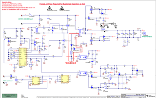
I removed the red boxed part, and add aux winding at output Inductor.

But, my circuit doesn't work.

If I don't connect aux winding, Vdd voltage reaches up to UVLO threshold voltage, and discharge above 8V.

But, if I connect aux winding, Vdd voltage doesn't reaches up to 12.7V.

It just on 2V.

I want to work my circuit.

please help me.

Best regards

  • Hi Doil,

    I believe it is much easier to generate the bias winding directly from the transformer as shown in the reference schematic. Since the transformer bias winding and PWM are both primary side referenced, you do not need to worry about maintaining the same galvanic isolation level required between primary to secondary which means you can have a tightly coupled bias winding. When you derive the bias winding from the output inductor, you now need to build galvanic isolation equal to the primary to secondary isolation in order to maintain consistent isolation. This will require separation between the coupled windings that is contrary to the need for tight coupling required for cross regulation. This techniques of coupled inductors is ok for sync buck converters because there is no isolation required. Coupled inductors are also used for multiple output forward converters but again, the idea is that the isolation barrier is not crossed since only the secondary is considered. Thanks for connecting through E2E.

    Regards,

    Steve M