Part Number: UCC28630EVM-572
Other Parts Discussed in Thread: UCC28631, UCC28630, UCC28634
Dear TI,
I am trying to design a housekeeping power supply for one of our products.
Requirement:
Input: 260 Vdc to 710 Vdc
Output: 12 V @ 1.5 A max.
I am using a EFD30/15/7 core (N97). I got done making a coupled inductor with Lm at 1460 uH. Leakage was 20 uH.
(I did Primary : 78 , Secondary: 9 and Aux: 10 ).
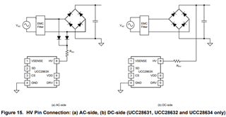
I am using the TI UCC38630 eval board .
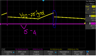
(I see the Vdd ramp up and down but won't start).
I am using the Eval board so that we can qualify before the layout.
Since all the controls are inside. I don't know what is going on and could use some help.
Thank you,
Warm regards,
Anirudh