This thread has been locked.

If you have a related question, please click the "Ask a related question" button in the top right corner. The newly created question will be automatically linked to this question.

BQ25792: USB PD test solution

Part Number: BQ25792
Other Parts Discussed in Thread: TPS25750, , USB-PD-CHG-EVM-01

Hi, 

We are thinking about developing a electronic load kind of system to test our USB C PD charger  and USB A ( unidirectional). 

The system is something like this, 


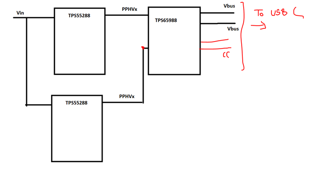
Now we want to test USB PD at full range and validate the circuit. 

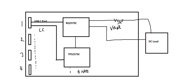
To test this circuit, Im planning a circuit something like 

My questions are 

a) Will the above solution will work? 

b) I need around 60W of sink from (BQ25792+TPS25750) can I achieve it ? 

c) Can you external uC and use BQ25792 as slave to read voltage /current etc? 

d) I see BQ252972 has D+ and D- pins for backward compatibility, does that mean I can use USB A BC 1.2 to operate the controller ?

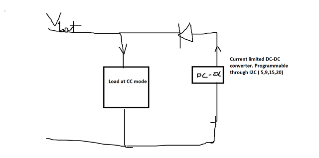
e) How to emulate battery. I want a constant current sink after regulating Vbat or Vsys to different levels  such as 5V, 9V, 15V, 20V ( provided by host at Vbus).   My thought was 

Need your suggestion.. Thanks 

  • Hello,

    The input system will work.

    a-b) What exactly are you going for with the load? Do you want the sinking power to go through the TPS25750 and then through the battery charger? This will work, you just need to connect the I2C lines as done in the USB-PD-CHG-EVM-01 reference design. The BQ25792 can do 24 V at 3.3 A in, however the TPS25750 can only handle 20 V. Therefore the max input current is 20 V 3.3 A or 66 W when BQ25792 and TPS25750 used together.

    c) You can use external MCU to control the BQ25792. Please note however that if the TPS25750 is connected to drive the BQ25792  (as in the USB-PD-CHG-EVM-01) there may be bus contention if they try to write at the same time. You can alternatively use the pass-through mode of the TPS25750 to control the BQ25792 through the TPS25750 rather than write directly to the BQ25792.

    d) The BQ25792 supports BC1.2 Detection through D+/D-.

    e) I would recommend a Keithley 2420 or some other piece of equipment that can act as a four quadrant power supply. If set into voltage mode on the Battery Output, the Keithley will regulate the battery voltage and sink the charge current into the equipment at the same time. As long as the Battery Voltage is kept constant, you will infinitely charge the "battery" (Keithley) at that voltage. Adjusting the charge voltage will allow you to see how the charge current responds to different conditions.

    Thanks,

    Mike Emanuel

    Please click "Resolved" if this answers your question.

  • Hi Michael,

    About c)
    How do I configure the TPS25750 to pass-through commands to BQ25792 resp. the CAT24C256WI EEPROM/Flash?
    In the following document I couldn't find anything with keywords like "pass-through" or "proxy" or something like that:
    TPS25750 Host Interface Technical Reference Manual

    I'm using a USB-PD-CHG-EVM-01...

  • Look for the I2CR and I2CW 4CC commands in the TRM.  These are the commands to pass I2C commands between the 2 I2C interfaces of the 750