This thread has been locked.

If you have a related question, please click the "Ask a related question" button in the top right corner. The newly created question will be automatically linked to this question.

TPS543C20A: Inductor current spike issue

Part Number: TPS543C20A

Hello

My customer is designing a POL using TPS543C20A for Vin=12V, Vout=1.2V and Iout(max)=12.28A.
They run WeBench steady state simulation, but are seeing large Inductor current spike as the attached results.
Where this spike comes from?
Do they have to use such an Inductor having large rated current to cover this spikes?
Or any ways to suppress the spikes?
WBDesign771_Steady State-1.pdf
Best regards,

K.Hirano

  • Hello,

    I am not certain why the WebBench simulator is calculating the large spikes in inductor current, so I will have to look into that in further detail. 

    As far as avoiding spikes in inductor current goes, having the RC snubber circuit on between SW and GND can help reduce switch node ringing and spikes in inductor current. Also, having high-frequency bypass capacitors placed close to the PVIN pin can help prevent this.  For inductor selection, it is important to pick an inductor that will not enter saturation which will cause a sudden drop in inductance and a spike in the di/dt of the inductor. All of these suggestions are implemented in the WebBench model, so I am unclear as to why the behavior is being demonstrated. Please allow me to explore this in greater detail. 

    Regards,

    Alec Biesterfeld

  • Alec,

    How is your exploration going?
    Have you found why the inductance current shows the spike at Webench simulation?

    Best regards,

    K.Hirano

  • Hi K.Hirano,

    Sorry for the delay. I have emailed Alec and he will feedback to you on June 3rd.

    US is on holiday these two days. Thanks for your understanding.

    Thanks,

    Lishuang

  • Hi K. Hirano,

    I investigated the schematic you used on Webench further, and it appears that the SW node voltage is irregular given the schematic you simulated. At lower duty cycles, advanced current mode control models are difficult to implement, so I may need to explore a further effort with the modeling team to correct the model based on physical data taken using the part.

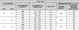
    Based on a 290nH inductor selection, the following table can provide you a ramp selection and output capacitance range at which the device will have stable operation (please note that the capacitance values are effective capacitance values and the design should account for derating when using these values):

    Please reach out regarding any help in designing with the TPS54C20A.

    Regards,

    Alec Biesterfeld

  • Hi ,

    Sorry that I will close this post first as there is no further concern . You can re-open it if you have any other question .

    thanks for understanding .

    BRs,

    Young