This thread has been locked.

If you have a related question, please click the "Ask a related question" button in the top right corner. The newly created question will be automatically linked to this question.

LM3423: LM3423 in Buck-Boost configuration, HSP pin gets sorted to GND inside the IC

Part Number: LM3423


Dear all,

I have a problem with this drive IC. The input is 48Vdc. The output has an LED panel operated by a voltage between 44..50V. The ideal drive would be 49V, where the panel consumes about 1.7A. 

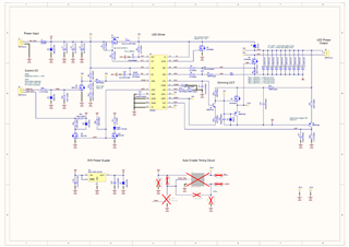
Based on the datasheet and AN-2010 appnote, I calculated all the parameters of the circuit.


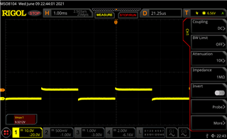
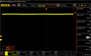
The phenomenon is that after the power supply appears, the LED panel flashes and then the HSP pin goes short, and the R4 resistor fries as a result. Unfortunately, the phenomenon took place in several panels. I checked everything, but I don't see the source of the error. Please help me.

The 555 timer is not currently fitted on the pcb, that will be an upgrade later.

BOM.xlsx

  • Hello,

    First look at the schematic and part list shows that your power FET's (Q2 and Q1) are rated at 100V and the voltage you can have at Vout is about 1V away from 100V.  This is too low rating of the FET voltage.  You will need to use 150V rating FET's.

    Thanks Tuan

  • Hello,

    Thanks for your answare! I will change Q1 and Q2 FET's to better ones.


    In the mean time, I did some testing. None of the transistors or diodes have been died on the PCB. But IS, VCC, GATE and DDRV pins are all shorted to GND inside the IC.

  • I got some spare parts. Saddly, changing the FET's to 150V types (SI4848ADY) does not helped. Even with low current limit, the LM3423 IC dies instantly. Again, IS, VCC, GATE and DDRV pins are all shorted to GND inside the IC.

    I still can't see what's wrong.

  • Hello,

    Thank you for letting us know about this. We will look into the problem and get back to you.

    Best Regards,

    Caroline

  • Hello,

    Can you please short out Q1 Drain and Source and re-test.  This time please monitor voltages feeding back to the LM3423 with scope captures to see if you are exceeding any voltages listed on the data sheet that causes the part to be damaged.

    Please also verify your calculations again and verify that the inductor that you use does not saturate with a current probe on it.

    Thanks Tuan

  • Hi,

    With Q1 D-S shorted out, the IC died instantly (I think it actualy died faster than before this way). This happend with PSU current limit was set to 100mA. So I was unable to measure anything.

  • Hello,

    The issue we have is that you are not using the IS resistor (R6) that we have on the IS pin on the AN-2010.  Please use the IS current sense as it was done on the application note.

    Thanks Tuan

  • Hi,

    Thank you! The IS current detection implemented with a 50mOhm resistor. As a result, the IC did not die! Originally, I wanted to take advantage of the Rdson sensing as I saw in the datasheet, but this is a more precise, better solution. I have attached the current state of the circuit:

    But my LED's are still not lit. Slight smile

    I can see this pwm signal on the DDRV pin when I connect my fucntion generator to PWM_IN, so I assume the "left side" of the circuit is working fine:


    The amplitude is about 6.8V, same as votlage in VCC pin. But between Q6 and Q5 (TP7) I can only see a verry small change in the voltage. It is not enough to operate Q5 mosfet:

    This "buck-bust dimming circuit" is not so simply. But I see no difference between my version and the AN-2010's circiut.

  • Hello,

    What is the GATE voltage looks like and what is the LED+ voltage looks like?  Is the regulator boosting up the voltage properly and the PWM dimming is not working?  You will need to do some debugging on your own here.

    Thanks Tuan

  • Hi,

    No, it is not boosting at all.

    VIN, EN pin: 48V.
    FLT and TMR pins: 0V, so there are no fault condition AFAIK.
    VCC pin: 7.5V, so internal supply is OK
    LED+: 48V constant
    GATE pin: 0V constant, no pulses, not a single one.

    In this condition, the pwm dimming signal from nDIM is transfered to DDRV.
    Also tried with hiher OVLO setting, but had no effect.

  • Hi,

    Did you try shorting out Q1 as I mentioned previously to do the test?  Other than that you will have to trouble shoot your board as to why it's not working and whether it's the modification related to the IS resistor.  You need to monitor all the pins voltages to figure out why it's in shut down.

    Thanks Tuan

  • Hi,

    Shorting Q1 makes no difference. I will re-check everything.

    I'm setting this thread to resolved, because of the original issue is got solved with your help.
    Thank you!