This thread has been locked.

If you have a related question, please click the "Ask a related question" button in the top right corner. The newly created question will be automatically linked to this question.

BQ34110: GPC tool: Unable to create CEDV parameters with acceptable SOC error estimation

Part Number: BQ34110

Hello all,

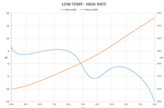
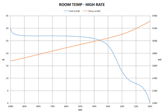
We uploaded the characterization log data from a high-power LFP cell to GPCEDV tool. The application uses quite high discharge currents (~2C average typical, up to ~6.5C average high) over a rather extended temp range (still meeting cell manufacturer's specifications). Unfortunately, GPCEDV is not able to fit all these data with a reasonably low SOC error estimation. We experimented with many different FitMaxSOC%, FitMinSOC%, LearnSOC% values but results are still not satisfactory.

We suspect that the source of this error is cell self-heating at cold (see graphs below). Is it possible to achieve convergence by trimming FitMaxSOC%, FitMinSOC%, LearnSOC% or we shall decrease discharge currents to e.g. 2C / 4C?

Could you please advise on the matter?


1803.log.zip

Thank you in advance

Dimitrios

  • Dimitrios,

    For a short term solution I would decrease the discharge rate for the characterization phase, please use a nominal rate to start with. In addition please post your log file so i can try to run them internally to see what kind of result I can get. 

    Thanks,

    Eric Vos

  • Vos,

    Thank you very much for replying. The log file is already attached (file 1803.log.zip). If you require any further information, please let me know.

    Regards,

    Dimitrios

  • I am attaching a screenshot which combines the Voltage vs RemCap curves for all of the six characterization measurements.

  • Since you are using 2V termination, the strange shape that is due to self heating and resistance changes in the cell due to stages of graphite and high discharge rates don't matter to much for accuracy, because your termination is still happening in a nicely decreasing portion of the curve.

    One problem with your settins is:

    FitMaxSOC% = 9
    FitMinSOC% = 7
    LearnSOC% = 2

    LearnSOC should be always betweeen Max and Min SOC, otherwise you are not fitting
    the portion of the curve (learn SOC) where you need the highest accuracy.
    I got better results (see attached) with:

    FitMaxSOC% = 5
    FitMinSOC% = 1
    LearnSOC% = 2

    One thing to mention is that room temperature has worse accuracy for some reason, which is unusual.

    Since this is a very high rate discharge, self-heating is a very important factor and it looks like

    high rate voltage actually goes higher then low rate voltage at the end, even though measured temperature increase is only slightly higher.

    Maybe temperature increase is not correctly measured.

    I wonder if location of thermistor and how well it is attached could be improved, or test could run in more realistic thermal

    environment (thermal box) that emulates actual device, so that cooling from the fan of thermal chamber does not interfer with the reading

    of the thermistor.

  • Hello Yevgen,

    Unfortunately, the actual cell pack and its enclosure were not ready at the time characterization began. However, the lug-type temperature sensor was very firmly attached to the cable lug and very close (~ 1cm) to the positive pole. Additionally, sensor was protected against direct air flow from the fan. So I tend to think that temp data are not grossly inaccurate.

    We made one more attempt to improve fitting accuracy, assuming that, at low temperatures, high rate discharges will not occur. Therefore, we copied the contents of lowtemp_lowrate.csv to lowtemp_highrate.csv. We uploaded this "new" log set to GPCEDV using various fitting parameters. The best result we got so far was by using FitMaxSOC% = 45, FitMinSOC% = 1, LearnSOC% = 1:

    EMF    3400    
    EDVC0    813    
    EDVC1    0    
    EDVR1    50    
    EDVR0    164    
    EDVT0    5171    
    EDVTC    3    
    VOC75    3316    
    VOC50    3291    
    VOC25    3237    
               
    file    SOC error, %    pass
    roomtemp_lowrate.csv    3.91088337221154    0
    roomtemp_highrate.csv    -3.45108699858289    1
    hightemp_lowrate.csv    -0.851390297966846    1
    hightemp_highrate.csv    -0.892860216595294    1
    lowtemp_lowrate.csv    -6.06922751851593    0
    lowtemp_highrate.csv    -6.06922751851593    0

    Rationale for using FitMaxSOC% = 45 is the fact that much smaller numbers ommit important log data, leading to unreasonably low EMF result. We are still worried about LearnSOC% = 1. Is this result OK?

    If results above are unusable, I am puzzled on what to do next because it seems to me that CEDV fitting algorithm needs a not only a strictly monotonic voltage vs DOD curve but it also requires these curves not to deviate from a second order polynomial form. If this is true, we should characterize using much lower discharge currents. Is this correct?

  • LearnSOC 1% just means that learning in your system will occure at 1% point. If this is acceptable and system will actually allow to discharge to this point, then it is a reasonable setting - just make sure you also change LeanSOC in the DF of your gauge.

    The rest of the results look reasonable for now.

    For the future it would make sense to use somewhat lower discharge currents to avoid very large IR drops and rises across resistance "humps" in LiFePO4/graphite system, which are not visible at low rates but can be very prominent at high rates as you have observed. You are correct that expected curves have to be monotonic and decreasing, at lest in the portion of the curve between max and min fit settings.

  • Yevgen,

    Thanks a lot for your invaluable input.

    Regards,

    Dimitrios

  • Yevgen,

    One last-minute question regarding future characterization attempts for similar applications: Is it acceptable for GPCEDV to use different discharge rates on one of temperature sets? E.g.:

    hightemp_highrate: 100A

    hightemp_lowrate: 40A

    roomtemp_highrate: 100A

    roomtemp_lowrate: 40A

    lowtemp_highrate: 50A

    lowtemp_lowrate: 20A

    Regards,

    Dimitrios

  • Yes, it is acceptable to use different rates for different temperatures. The tool does not make any assumptions about the currents, it takes them directly from each log file. So it makes sense to use lower rate at low temperature, for example to reach larger portion of total capacity during discharge if it terminates too early at high rate.

    Regards,
    Yevgen