This thread has been locked.

If you have a related question, please click the "Ask a related question" button in the top right corner. The newly created question will be automatically linked to this question.

BQ25730: Datasheet refers to non-existent register EN_FAST_5MOHM

Part Number: BQ25730
Other Parts Discussed in Thread: BQ25731,

Hello,

  In evaluating this part I have not been able to understand the logic behind the input current limit function (IIN_DPM / IIN_HOST). Input current sensing and limiting is described in the datasheet in terms of a register which does not exist in the register descriptions, nor anywhere I can find on Google (EN_FAST_5MOHM). The BQ25731 datasheet also seems to have the same issue.

  The part supports a charge current up to 16A, so I am confused as to why the input current sense's maximum clamp is 10A, as there is no other source of charge current, and the DPM loop maximum current is similarly limited. I intend to disable the input current regulation loop and rely only on VSYS regulation in order to overcome this limit while using a 5mOhm resistor in order to ensure a large enough signal for the inductor current regulation loop. However it would help if the datasheet was rewritten a little to make this design decision clear and remove reference to this missing register.

  I would appreciate it if someone could confirm my understanding is correct, and that the part will behave as expected.

Thank you.

  • Hi Paul,

    Thanks for reaching out. Yes, you can disable the IINDPM loop and rely on VINDPM for input source protection. 

    We have the BQ25730 EVM for evaluation if necessary. 

    https://www.ti.com/tool/BQ25730EVM 

    Thanks,

    Peng

    *If my answer solves your question, please press "This Resolved My Issue" on the thread. 

  • Thank you Pengzhao,

      Would it be possible to have the relevant section of the datasheet updated to either add the registers referred to, or reword the section they are included in?

    Thank you.

  • Hi Paul,

    I will take a note and discuss internally. However, it is not something that can be done in a day or two.

    For now, please disregard that bit. You can take it as case 3 in the datasheet:


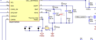
    On the EVM, we also uses IADAPT pin resistor > 160k. In generally, the more integrated an IC is, the more you want to refer to the EVM.

    Thanks,

    Peng

    *If my answer solves your question, please press "This Resolved My Issue" on the thread. 

  • Thank you Pengzhao,

      I understand it will take some time before the datasheet could be updated. I have marked your reply as answering my question as disabling the loop should allow me to produce the expected output power. We will indeed refer to the EVM.

      I would still be interested to learn why the DPM level is set so low though. Was it considered more important to have low current accuracy than high current limiting? Our customers may provide their own adaptors, so in this case DPM is not useful to me, but in another use case it would be useful to be able to extend the range to 15A.

    Paul.

  • Hi Paul,

    Actual the DPM level of 10 A is already on the high side for most of our chargers. It is set at this level as this is what we see the market demand is (covers the power level).

    The IIN_DPM loop is another loop within the charger. The wider the range, the more resource, cost, and complexity will be needed to design the part. A typical DC-DC converter (non-battery charger) will just have one loop (a single loop to control VOUT, sometimes even require external compensation) while our chargers incorporate various control loops for operation. The result of that is a charger that is ease to use and design for our customers.

    Thanks,

    Peng

    *If my answer solves your question, please press "This Resolved My Issue" on the thread. 

  • Hi Paul,

    I misread your question at the beginning so let me do a little bit of clarification. You asked why the input current sense maximum clamp is 10 A and charge current of 16 A is capable. The reason it is because it is a DC-DC converter and you can have higher output current for less input current.

    In an ideal no-loss DC-DC converter, PIN=POUT. Power in a DC circuit is P=IV. As an example, in a theoretically percent converter (not the BQ25730), if you have 16V in and you need 1V@16A output, that translates into a input current of 1 A.

    If you disable IINDPM loop and rely VINDPM for input source protection, you would need to do testing/verification on the system level to ensure performance level is acceptable for your application.

    I hope this helps,

    Thanks,

    Peng

    *If my answer solves your question, please press "This Resolved My Issue" on the thread.  


  • Hi Peng,

      I do understand that it is a DCDC converter, but as it is also a buck-boost I would have expected the limits to be symmetric. After all it is as valid to have 20V in, 10V out as it is to have 10V in, 20V out.

      Thank you for your responses. I will indeed be carrying out dynamic tests of the input control loops in the coming few weeks.

    Thanks again.