Other Parts Discussed in Thread: BQMTESTER, BQ40Z50-R1
Hi
I am planning to use BQ20Z655-r1 IC in designing a battery Pack.
Could the IC can be used for production,
Whether the software and other requirements(Queries) will be supported by Ti.
This thread has been locked.
If you have a related question, please click the "Ask a related question" button in the top right corner. The newly created question will be automatically linked to this question.
Hi
I am planning to use BQ20Z655-r1 IC in designing a battery Pack.
Could the IC can be used for production,
Whether the software and other requirements(Queries) will be supported by Ti.
Hi
I am designing a schematics for 4s1p Battery pack using BQ20z655r1.In this i have the following queries which is listed below
1.LED is not needed for indicating the battery percentage, So the LED pind and LED out can be grounded.
2.The PFIN pin is necessary to be connected to indicate the Secondary Protection input.
3.The DISP pin can be connected to ground if it is unused.
Hi
I am designing a 4S1P Battery pack using BQ20Z655-r1.
In this i dont need the LED pins to display the battery percentage, So whether the LED1 to LED5 and DISP can be left floating.
2.PMS If connected to Pack Pin,The precharge can be carried out by Charge FET right??
3.CE can be left unconnected? whether it affects the design. Also Why CE is needed.. Could you breif it??
Hello Anandan,
Sorry i was looking at the wrong part pinout. Both pins must be connected. Connect PACK to PMS to allow 0v precharge.
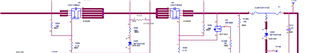
Connect CE pin based on desired functionality
The bq20z655 EVM design is the best reference. You can use those input connections if the described functionality is a don't care.
HI Shirish
I have connected the FUSE as Follows in the Load Current Path.(Instead of connecting between Positive cell and FET,I have connected on other end between the pack voltage and FET)
Whether my design is correct ??
Hello Anandan,
There are multiple considerations for FUSE placement. The purpose is safety. The Positive cell is the first point from where current can flow. If the battery is designed such that there is no other short possibility(or application of external voltage) in the path between Positive cell and Pack, then I do not see an issue..
Hi
i am using BQ20Z655-R1 IC for building 4s1p pack
In this i need to charge the battery during the precharge mode.
So I can use for CHG-FET for charging the battery during precharge based on the software configuration.
In that time can I make ZVCHG(precharge FET section as DNP. and connecting the PMS to VSS to disable 0V precharge.
will it be ok to use in the design as suggested.
I checked the datasheet and it looks like if you plan to use CHG-FET for precharge then PMS is to be connected to PACK.
See "Pin functions" section of datasheet which states "Connect to PACK to enable 0-V precharge using charge FET connected at CHG pin."