This thread has been locked.

If you have a related question, please click the "Ask a related question" button in the top right corner. The newly created question will be automatically linked to this question.

LM5157-Q1: Output ripple with LM5157 and LM51571

Part Number: LM5157-Q1
Other Parts Discussed in Thread: LM5157, TPS55340, LM5156,

I am designing a product that uses a 28V, 500mA supply for a GaN transistor based RF amplifier.  This is a noise sensitive application where the ripple in the supply must be known. The LM5157X would seem a good candidate as it has the optional spread spectrum dithering to spread output ripple energy over frequency. 

However, there seems to be no quantitative information in the datasheet about output voltage ripple.  The closest thing to this issue is the statement "The output capacitor value can be selected based on output voltage ripple...", but, no information on output ripple as a function of this capacitance or any other parameters is given. 

Is information on the output voltage ripple of the part available?  If not, I will have to select another part that is specified for output ripple. 

Thanks

Farron

  • Hi Farron,

    the Output ripple is mainly defined by the Output Capacitor and general setting of the DC DC converter and not from the LM5157 Device specific parameters. Therefore this are not shown in the datasheet.
    But you can find a lot of details in the Power Design Seminar material.

    Please check here: Power supply design seminar resources (ti.com)

    Esp. for the Boost you can look into Under the Hood of a DC/DC Boost Converter in the 2008 section.

    https://www.ti.com/seclit/ml/slup270/slup270.pdf

    Here you find a chapter: Selection of an Output Capacitor on page 14

    Best regards,

     Stefan

  • Hello Stefan:

    Thanks for the prompt answer.   It leads to a few other questions:

    1.  The references provided may have excellent information, but much of that information is over a decade old and seems to predate the use of spread spectrum dithering to reduce discrete frequency spurs.  Is there information available for noise levels when the dithering option is used on the LM5157?

    2.  In the WEBENCH application, no option is given for simulation with the LM5157 (it is grayed out).   That simulation would apparently be needed to experiment with ripple as a function of capacitance values.  Is there an estimate for when WEBENCH may be updated to allow simulation with this relatively new part? Would these models provide for the noise with dithering?

    3.  The issue also arises as to the best simulation platform.  Is there a way to vary part values from the WEBENCH generated schematic and run the sims with these different values?

    4.  TI TINA SPICE has macro models for many switchers, but not for the LM5157, or for its predecessor part, the TPS55340.   It is nice to be able to run sims in TINA for these parts, for example, to also include additional LC filtering on the switcher output and get accurate transient mode sims of final ripple.  This would also be the only way I know to get noise spectrum over frequency, particularly with dithering, which can be attained with the built in FFT of transient mode output.   Will these models become available for TINA?

    Thanks,

    Farron

  • Hi Farron,

    referencing my answers to your questions:

    1. Have you already checked the Technical Documentation on the product page? There is a reference to:
      EMI Reduction Technique, Dual Random Spread Spectrum
      May this gives you the required information.

    2. LM5157 simulation in Webench is still in development and should be available end of July
      To get information about the ripple I would recommend to use the EVM. This would give a the most accurate results.
      But you may use the LM5156 as described here:
      LM5157-Q1: SEPIC WEBENCH simulation - Power management forum - Power management - TI E2E support forums
    3. It will work when the Webench simulation is release. Meanwhile the TI-Spice simulator or the EVM can help.

    4. TI is now switching to the newer Spice Simulation Tool – TI PSpice. Therefore the LM5157-Q1 only provide Spice Models for TI Spice.
      The TI Spice simulator can be downloaded from the TI web page. A link can be found the product page section: Design Tools and Simulation. Here you can also find the TI SPcie models
      LM5157-Q1 data sheet, product information and support | TI.com

    Best regards,

     Stefan

  • Hi Farron,

    did the answer give you all the required information?

    If yes, it would be great to close the issue with clicking on the resolved button.

    Thanks,

     Stefan

  • Hello Stefan:

    I may have all the information you can give me, but I had not closed just in case more information can become available.  Let me add to my explanation and questions below to make this special case more clear. 

    I am an RF and low noise consulting designer who uses a lot of TI parts for my clients, and am often in the position of having to pursue detailed noise issues about those parts.  I have found that those more esoteric questions often are passed on to specific experts (such as Dean Banerjee, author of the best synthesizer book in print,  for synthesizer noise), and was wondering if there is a similar expert for the switching noise who might get involved here.  

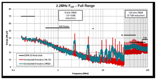
    From the app note you mention above, "EMI Reduction Technique, Dual Random Spread Spectrum", I copy the below figure for the LM5156 switcher from the Summary section.  Some key points are:

    1.  With a measurement BW of 120kHz (a more realistic BW than 9kHz for true behavior, though still not wide enough to fully capture the sharp edged noise), the spread spectrum can be counted upon to reduce switching spurs of the 2.2MHz switching frequency and its harmonics by only about 5dB.  

    2.  The measured noise at 9kHz BW is not to be trusted when designing for goals other than regulatory compliance in a specific case using a 9kHz BW.  For example, it shows spread spectrum improvement to be 10dB to 15dB.  It also shows the 2.2MHz switching noise when NOT in spread spectrum mode at +47dBuV, which is only 0.224mVrms or 0.633mVpp.   I've never seen a  switcher with switching noise this low.  It is typically in the 20mVpp to 50mVpp range, and sometimes as bad as 100mVpp. Since the 120kHz measurements are nominally 15dB to 20dB higher in noise, that would indicate a 2.2MHz spur in the range of about 4.7mVpp, which would still be unusually low for a switcher, though I have had similar numbers for an LC filtered switcher. 

    In the current project I am not designing for regulatory compliance using these artificial bandwidth limits.  I am designing for spectral purity in the final supply of ultra-low noise frequency sources like crystal oscillators, excellent VCO's, and low noise synthesizers.  So, what I am seeking to get at are the required stages of linear regulation and LC filtering that I will need to take a switching supply to an ultra-low noise supply for these frequency sources. 

    I may need two layers of linear regulation plus LC filtering to suppress these switching spurs down to an ultra-low noise regulator floor that is in the range of 1nV to 2nV per root Hz (0.69uVrms or 1.95uVpp at 120kHz).  But, if I can use just one linear regulation layer plus LC filtering, I improve cost, board area, and supply efficiency.  This seems to depend on how well the spread spectrum does spread out the spur noise.  

    If the real switching noise in the LM5157 is 50mVpp, and this is realistically improved only 5dB by the spread spectrum BUT the spread spectrum can be counted on to prevent very narrowband spurs (which allows comparing to a floor much higher than 1Hz), then it is effectively 28mVpp.  To get down to 1.95uVpp floor of the regulators (in 120kHz BW) takes a minimum of 83dB power supply rejection ratio at 2.2MHz.  The regulator can provide around 60dB to 70dB, and a single stage of LC filtering can provide the rest. 

    But, the spread spectrum may still allow for narrow spurs that hide under the noise floor of a wideband measurement, so the question would be how bad are these?  A low noise frequency source designer does NOT get the luxury of hiding these under a wideband floor, because the industry standard for measuring phase noise is a 1Hz wide phase noise measurement in a phase noise test set.  Such a measurement precisely exposes narrowband spurs. 

    So, the bottom line would seem to be that with spread spectrum (and no locking to accurate crystals to create very focused spurs), a single stage of low noise linear regulation supplemented by an LC filter will get switching noise down to the point of being negligible IF there are not spurs hiding under the noise floor.  To tell this would probably require that the spur measurements were available in 1Hz bandwidth measurement form.  Are such measurements available?

    Thanks,

    Farron

  • Hello Farron,

    As far as I know such measurements are not available. In your case, it might be more useful to use gate resistors and snubbers on the switch node as well as small size input and output capacitors that filter some of the high frequency noise before leaving the converter. We normally do not add these high frequency capacitors close to the power stage and connected shortly to PGND, as the values need to be tested in the frequency range. As the main purpose of the EVMs is to show the functionality of the device, they are not created for minimum noise.

    So the addition of the above mentioned components and in addition increasing the amount of output capacitance to reduce the ripple and therefore the spurs at the switching frequency, might be more helpful in your design than using the DRSS feature.

    In addition, I will check if it is possible to reduce the filter bandwidth for above measurement.

    Best regards,
    Brigitte

  • Hi Brigitte:

    Thanks.  I will leave the issue open a few more days to see if anything more comes to light on the measurement bandwidth. 

    Noise floors as low as I seek here are not the norm, so it is not surprising if there is not much information available.  I guess the custom work needed is among the reasons why low noise signal generators cost tens of thousands of dollars. 

    Best,

    Farron

  • Hi Farron,

    just wanted to follow up and that thread to avoid it got out of vision. Do you have already new results? Should we close this thread or would you still like to keep it open.

    Thanks,

     Stefan

  • Hi Stefan, yes, we can close it now.  Thanks, Farron.