


Other Parts Discussed in Thread: CSD18563Q5A, , LM61460, LM76005
Hello there,
Need help ASAP please!
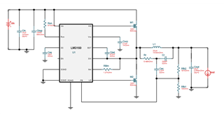
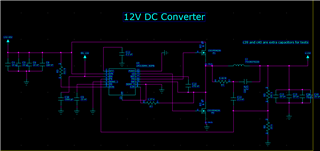
I designed in the power designer tool a circuit to convert 14-40V DC to 12V DC with a maximum output current of 5A.
I connected a 12V led to the output. When i turn on the input supply it blinks a few times but most of the times it doesn t work at all.
I had this same layout and circuit that worked before but when i reproduced it in a new pcb it doesn t work and i don t know why.
Some quick measurements with 15.2V at the input:
Cvcc=6.2V (fix value)
SS = instable -> 0 or 300mV
Cbst (between SW and BST) = instable -> 0 or 3V
SW = instable -> 0 or 2V
Output = instable
The gate signals are instable too.
I can t share all the circuit but you can see the relevant part.

UPDATE:
Removed the parallel capacitors at the output and I left only one and started working with 11.3V - 11.6V of output (it fails after 1 minute)
I use ceramic capacitors with low ESR. How can i solve this?

