This thread has been locked.
If you have a related question, please click the "Ask a related question" button in the top right corner. The newly created question will be automatically linked to this question.
Hi team,
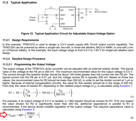
Currently I am using TPS61071 for a project with the supply of 2 cells batteries and the voltage out is 3.3V, but with a new battery 1 battery can have a voltage of up to 1.65V so 2 cell batteries there will be an equivalent voltage of 3.3V, when the voltage of the battery is 3.3V equal to the output voltage of the TPS61071 so at this time the output voltage is not regurator so my circuit is seriously affected, I want to find a the IC has the same pin connection as TPS61071 and has a voltage stabilizer function even if Vin >= Vout (about 0.5V).
Best Regards !
Han,
do you need regulated 3.3V output even VIN=3.8V? if so, you would need to buck-boost converter, instead of boost converter like TPS61071
Hi Jasper Li,
thank for your reply, I am using 2 cells batteries and Vout is 3.3V,i think the Vin max is 3.4V .I have also made a PCB now, so I would like to find a substitute.
what about TPS61098? the output voltage will be 3.4V if the input is 3.4V, but VOUT=3.3V if input is lower than 3.3V.
Hi Jasper Li,
Thanks for your suggestion, but it can not replace for tps61071 on the board now being mass production. vout=3.4 when vin=3.4 is ok but i want to 3.4 vout is stable when vin have a small ripple .do you have any other suggestion, or solution to stabilize output voltage for tps61071 when vin > 3.3v and have a small ripple(60mv 100Hz)
Thanks and Best Regard
Hi Jasper Li,
Thank for your suggestion,
In that case, I would like to try that as well, but the maximum operating voltage of the MCU is 3.6V, and if Vout is set to 3.5V, for example, due to the error of the feedback resistance, Vout may reach or exceed 3.6V. By the way, for example, if Vout is set to 3.5V and the error of feedback resistance is 1%, what is the minimum and maximum value of Vout? Is there an individual difference in TPS61071?
Thanks and Best Regards !
Hanh,
if the VOUT is set to 3.5V, the maximum value should be 3.57V considering the IC and resistor variation. and the minimum value is 3.43V
it should be OK for your application.
BTW, is the maximum value of the battery voltage is 3.4V? NOT 3.3V?
Hi Jasper Li,
Please tell me how to calculate maximum and minimum the Vout ?Present i confirm on new manganese battery is 3.3V.
Show as below
With R1 = 1M, R2 = 180K, CparR1 equal 0.2pF.
But actually with that value the output voltage response is not very good, I used 82nF capacitor and saw the load response improved. How I have to understand and use that capacitor properly? with 3.3V output my load current consumes about 25mA, LED(10mA) blinks with 2.5s cycle
Best and Regards
Hi Hanh,
the voltage is mainly defined by the VREF variation and feedback resistor. as the VREF and resistor variation are both 1%. the output voltage variation would be +-2%.
I'm concerning the stability of the boost after adding 82nF capacitor. refer to this application note to select the Cff Optimizing Transient Response of Internally Compensated DC-DC Converters (Rev. B)
what kind of waveform did you observe with and without Cff?
Hi Jasper Li,
Thanks for your reply
sorry but I still can't get the waveform right now.
I am planning use LM2621 , when Vin > Vout ( example Vin=3.4V) how many volts will be on the output?
Is the LM2621 a step-up / step-down IC?
Best Regards !
Hi Nanh,
it is a boost IC. the output will be also higher than 3.4V if the input voltage is 3.4V.
if you need a regulated 3.3V at both VIN> VOUT and VIN< VOUT condition, I would suggest a buck-boost converter such as TPS63900.
Hi Jasper Li,
Thanks for your reply. I also try with SEPIC regulator of LM2621 as show below schematic but was not successful (test condition is Vin =3.3V,Cin = 100uF, Cout=22uF, No load)
Thanks for of your suggest , I will check TPS63900 of spec now
Best Regards!
Hi Jasper Li,
with the Vin = 3.0V, Vout = 3.2V test circuit as sho below
for test transient load response I have LED blink with frequency ( 200mS ON, 280mS OFF)
with Cff = 10pF, the waveform of PreAmp_Out as show below
with Cff = 47nF, the waveform of PreAmp_Out as show below
Best Regards !
Hi NanH,
the Cff increases the bandwidth of the circuit, which also improve the load transient.
but too large Cff could lead to stability issue, or less stability margin.
you can also increase the COUT to improve the load transient.
Hi Jasper Li,
By the way what is the behavior of TPS61071 when VIN is near or higher than VOUT.
Best Regards !
Hi Jasper Li,
One more problem please help me is when the supply voltage ripple is big the output will have big ripple ? the Cff can to improve output ripple in this case?
Best regards!
Hi Nanh,
the VOUT may be out of regulation if the TPS61071 VIN is closed to VOUT because of the minimum off time.