This thread has been locked.

If you have a related question, please click the "Ask a related question" button in the top right corner. The newly created question will be automatically linked to this question.

TPS61165: Calculation of the ripple current

Part Number: TPS61165

Hi everyone,

I've got a question regarding our implementation of the TPS61165, which we use to drive 8 leds in parallel (2x4). The current per line is 160mA, so 320mA in total per driver, with 4 leds of Vf = 6V, so Vout = 24.2V if we had the VFB of 200mV, with Vin = 15V.

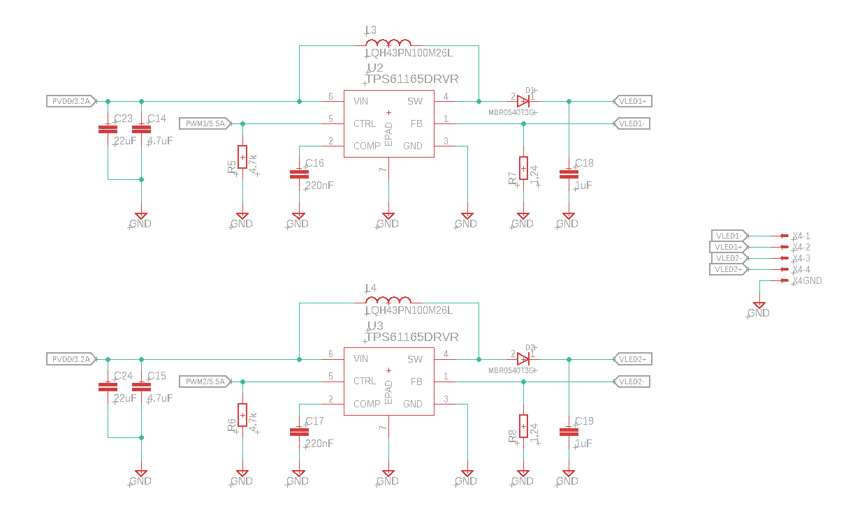
Below is the schematic of our implementation, with two drivers (each one control a different chain of white leds):

From my calculation, I've got a ripple current of Ip = 494mA, which is more than 100% of the leds current. Am I missing something here? Can someone validate that I didn't make any mistake in my choice of components? Our prototypes work well, but I would like to validate this before going to production.

Thanks for reading me,

Yoann

  • Hi Hardy could u help in this case

  • Hi Yoann,

    This is inductor peak to peak ripple current, which is the current flow through the inductor but not LED.

    For your case with VIN=15V, VOUT=24.2V, IOUT=320mA, we can do a simplified calculation with 90% efficiency that here need IIN= VOUT * IOUT / VIN / 90% = 573mA. Plus half Ip that the maximum current through switch FET is around 800mA, which is below 1.2A switch current limitation. I think TPS61165 is OK for your application.