This thread has been locked.

If you have a related question, please click the "Ask a related question" button in the top right corner. The newly created question will be automatically linked to this question.

BQ24070'S questions

Other Parts Discussed in Thread: BQ24070

       Questions as below:

1.       When BQ24070 execute “THERMAL SHUTDOWN REGULATION”, how many seconds(Response time) will Q1 and Q3 be turned off after temperature exceed 155C?

2.      In the page6, it specifies the Q1 and Q3 for THERMAL SHUTDOWN REGULATION. But we can not find Q3 in the block diagram. Does it only have Q1 and Q2?

3.       For Short-Circuit Recovery, there are two descriptions as follows.

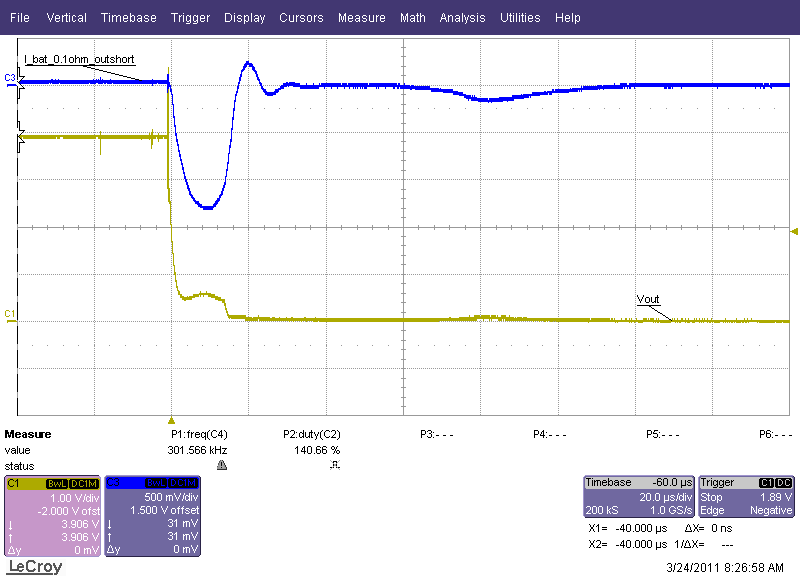
If the output drops below  1 V, an input short-circuit condition is declared and the input FET, Q1 is turned off. How many seconds(Response time) will Q1 be turned off after output drops below  1 V?

    If the output drops 200 mV below the battery voltage, the battery FET, Q2 is considered in short circuit and the battery FET turns off.  How many seconds (Response time) will Q2 be turned off after output drops below 200 mV?

 Could you kindly offer the answer! Very thanks.

  • Brian, these are good questions, but what is your application concern?

    Answer 1)  First, it is not practical for the charger to ever hit 155C since there is a thermal regulation loop at 125C that will adjust the current totally off.  Thus the only way is for an external heat source to heat up the IC to this temperature.  If this was the case, the delay is irrelavent since the delay after the detection threshold is reached would probaby be in the sub millisecond range and it would take 100s of milliseconds to heat up the IC.

    Answer 2) Q3 is always disable in this part since it does not have a separate USB input.

    Answer 3a) This is a current source so if a short is applied the current never increases so it is not like a critical issue where high current is delivered and one wants to minimize the time.  The comparator and logic are in the microseconds, but the control loop drive to turn the FET off is in in the low miliseconds range, <10ms.

    Answer 3b) if input is applied then the bat short circuit delay is expired and the delay is 10us to start turning off the FET and another 10us until the BAT FET is off. see photo.

    If just the battery is applied and a short on the out pin is applied then the time is a function of the DPPM capacitor.  After the DPPM pin charges to 1V (starts to charge after short is detected) then it takes 20us.....so the dominate time is the time for the DPPM pin to charge to 1V.