This thread has been locked.

If you have a related question, please click the "Ask a related question" button in the top right corner. The newly created question will be automatically linked to this question.

UCC28881: How to calculate power dissipation and junction temp for UCC28881?

Part Number: UCC28881

Hi Team, 

My customer is asking how to calculate power dissipation and junction temp for UCC28881?

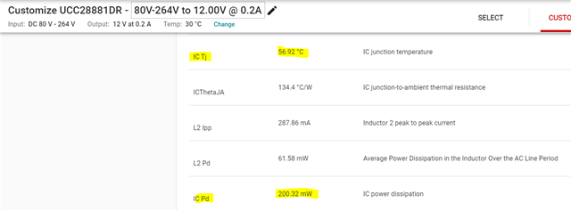
I think normally following formula is used to calculate Tj(max), but how can customer calculate power dissipation? I couldn't find it in datasheet.

Tjmax[℃] = Ta []+ RθJA[/W] * PD[W]

I know Webench is one way to estimate power dissipation and Tj, please let me know how can I get it by hand calculation.

Thanks.

Regards,

Jo

  • Hello.

    Your calculation seems to be correct for calculating the maximum junction teampature.

    It looks like you need to calculate the power dissipation of the IC. 

    You can estimate the power dissipation of the UCC28881 using the following equation.   

    Estimate the switching transitions (tr) of the FET to be 100 ns.  The maximum switching frequency (fsw) of the UCC28881 is roughly 62 kHz.  The maximum average output current I(avg) for this design should be 225 mA.

    Pd = I(avg)*Vin +((Iavg)^2)*Rdson + 2*(Limit/2)*tr*fsw, please note this is an over estimate.

    After the Pd is calculated you can estimate the maximum junction teampature.  I recommend that you design for 75% of the rated ICs maximum.

    Regards,

  • Hi Mike, 

    Thanks for the reply.

    customer's condition is AC80~264V to 11~13V 200mAmax. (Low-Side buck converter)

    Pd = I(avg)*Vin +((Iavg)^2)*Rdson + 2*(Limit/2)*tr*fsw

    I think  I(avg)*Vin will be 52.8W(264V*200mA), a quite large value. So I want to confirm with you if the formula is correct or having typo?

    And by 2*(Limit/2)*tr*fsw, do you mean 2*(ILimit/2)*tr*fsw?

    If yes, ILimit at 25C is 440mA(typ.), is it correct to use this value to calculate?

    Thanks.

    Regards,

  • Hello,

    ILimit/2 is because the current during the switching losses is approximated to be a triangle.  It is multiplied by a factor of 2 because there are switching losses on turn on and turn off.  You are correct there is a Vin term missing.  I aslo found a few more typos.  I thin the following equations is a better estimate which includes the RMS current of the FET.

    Pd = ((ILimit*(Dmax^0.5))^2)*Rdson + 2*(ILimit/2)*Vin*tr*fsw

    You are correct about the ILimit being used from the data sheet.

    Regards,

  • Hi Mike, 

    Thanks for the reply.

    I have three questions about the new formula. 

    1.When I use Vin=264V to calculate Pd, Pd will be around 2.144W. However, Webench shows only 0.2W. I think the value in Webench is more reasonable, could you confirm which is correct? Formula or Webench?   

    2. When I use Vin=264V to calculate Pd, Tj will exceed absolute maximum rating. Is there any incorrect in my following calculation? 

    "Pd=((440mA*(55%^0.5))^2)*14ohm +2*(400mA/2)*264V*100ns*62kHz"=1.49W+0.655W=2.144W"

    "Tj=Ta+RθJA*Pd=30C+134.4C/W*2.144W=318C"

    3. If possible, can you tell us how did you derive following formula? Or if Webench below shows the correct value for Tj and Pd, I'll ask customer to use Webench to estimate them. 

    Pd = ((ILimit*(Dmax^0.5))^2)*Rdson + 2*(ILimit/2)*Vin*tr*fsw

    Thanks.

    Regards,

    Jo

  • I think your RMS power dissipation is off.  Could you double check that please?

    Regards,

  • Hi Mike, 

    I didn't get what you said. Could you kindly answer my questions above?

    I think the calculation is as same as the formula you provided. 

    If you are talking about Webench, could you point it out specifically? Below is the Webench link I used. 

    https://webench.ti.com/appinfo/webench/scripts/SDP.cgi?ID=CAAA52A11B37AFBE

    Thanks.

    Regards,

    Jo

  • ((440mA*(55%^0.5))^2)*14ohm

  • Hi Mike, 

    I still don't get what you mean.

    I looked back what you said at the first, and I think first item of formula should be I(avg) instead of ILimit. By using I(avg) for first item, Pd became around 1W. However, Tj still become unreasonable value if we use Pd=1W to calculate. 

    Pd = ((I(avg)*(Dmax^0.5))^2)*Rdson + 2*(ILimit/2)*Vin*tr*fsw

    Could you help confirm if above formula is correct or not? 

    Or if Webench is showing the correct result, please let me know. I'll just ask customer to confirm Tj and Pd with Webench.

    Your help is really appreciated.

    Regards,

    Jo

  • Hello,

    Sorry about the confusion and the error in the the equation.

    This equation is incorrect.

    Pd = ((I(avg)*(Dmax^0.5))^2)*Rdson + 2*(ILimit/2)*Vin*tr*fsw

    This equations is correct.

    Pd = ((440mA*(55%^0.5))^2)*14ohm + 2*(ILimit/2)*Vin*tr*fsw

    ((440mA*(55%^0.5))^2)*14ohm = 248 mW

    If you use the second Pd calculation your thermal calculation should be more accurate.

    Sorry about the mistake.

    Regards,

  • Hi Mike, 

    Thanks for the confirmation. 

    But Pd still becomes large value which cause Tj become unreasonable value if I use following equation.  

    Pd = ((ILimit*(Dmax^0.5))^2)*Rdson + 2*(ILimit/2)*Vin*tr*fsw

    Pd will be more reasonable if I use Dmax^2 instead of Dmax^0.5 for "((ILimit*(Dmax^0.5))^2)*Rdson" term. 

    Could you kindly help confirm the whole formula if it is correct again? 

    Customer is waiting for answer of calculation for Tj and Pd, but the calculation result of above formula doesn't make sense so I haven't been able to share the formula to customer. 

    And I have another two questions about Webench. 

    1. UCC28881 on Webench is high-side buck topology, but customer is using UCC28881 as low-side buck topology, 

    will the simulation result for Pd be the same for both high-side buck topology and how-side buck topology? 

    2. Will the external components value(resistor, capacitor, inductor) affects simulation result for  Pd? I'm asking because the formula Mike provided have no parameter for external components value but the Pd simulation result actually changed after I changed the value of Cfb.

    Thanks.

    Regards,

    Jo

  • Hello,

    I reviewed this in more detail and worked out the power dissipation based on minimum and maximum output voltage, ILimit, tr and duty cycle at min and max line.  Please see the attached PDF for details. 

    Mathcad - UCC28881 Eval 6 10 21B.pdf

    In this example I estimated the power dissipation worst case to be roughly 600 mW.  Based on this power dissipation to keep the maximum junction teampature under 125 C would require the ambient teampature in the design below 49 degree C.

    Regards,

  • Hi Mike, 

    Thanks for sharing the calculation. I made a mistake on Duty cycle. I used the value in electrical characteristic table. 

    Customer will use the formula to calculate heat dissipation. 

    I'll let you know if there's any further questions.

    Thanks.

    Regards,

    Jo

  • Hi Mike, 

    My customer wants to confirm about ILimit term in the formula. 

    In normal condition, Iout=Iavg will be 120mA for customer's application. 

    Is it correct to use Iout=Iavg=120mA to replace ILimit(440mA) to calculate power dissipation in normal condition(overcurrent not triggered)?

    Thanks.

    Regards,

    Jo 

  • Hello,

    If the customers output current is a 120 mA than his current is a triangle and the RMS current is ILimit*(D/3)^(1/2)

    I limit is triggered every switching cycle and does not trigger and over current.  What the UCC28881 has is inductor current runaway protection that is described in section 8.4.5 of the data sheet.  If the ILimit is trigger during Ton-to the device will go into  inductor current correction to ensure the current does not run away.


    Regards,

  • Hi Mike, 

    Thanks for the reply. I want to confirm with you about the calculation. 

    So are you saying that RMS current can be calculated by ILimit*(D/3)^(1/2). 

    And RMS current can be used to replace ILimit in the formula to calculate power dissipation in normal condition?

    Thanks.

    Regards,

    Jo

  • Hi Mike, 

    Looking forward to your reply. Thanks.

    Regards,

    Jo

  • Hello,

    You were correct and should be able to calculate the power dissipation with the information that is given.

    Reegards,