This thread has been locked.

If you have a related question, please click the "Ask a related question" button in the top right corner. The newly created question will be automatically linked to this question.

TPS23753A: VC電流のばらつき

Part Number: TPS23753A

TPS23753Aを使用して、PoEスプリッター、Vout=12vを設計しました。

通常動作時にICの4番Portに流れるVc電流にばらつきがあり、数十mA流れるスペックオーバーの場合もあります。

Vc電流に数十mA流れる場合は、Q1が熱により故障する症状が起きています。正確ではないかもしれないが、約3割で発生。

Vc電流に過剰な電流が流れる条件は何でしょうか?

Remark

・回路図を添付します。(一部抜粋)

・D1を現在の12vから9.4vに変更するとVcの電流が下がります。

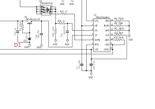
・11番Portのクラスは、現在は3です。ただし負荷は3.8W程度しか消費していません。

以上です。

  • Konichiwa Hideki-san,

    Boku wa tsukoshi nihongo wakarimasu. dakara, boku wa TI FAE ni hanashimasu. arigatogozaimashita!

  • Darwin san

    Thank you for your strong supports!

    I write in English.

    I designed a PoE splitter, Vout = 12v, using TPS23753A.

    A large current may flow through the 4th port of the IC(Vc).

    It may be over spec.(I measured 10mA-60mA.)
    In this case, there is a symptom that Q1 fails due to heat.
    What are the conditions under which an overcurrent occurs in Vc?

    Remark
    Changing the Zener voltage of D1 from 12v to 9.4v reduces the current of Vc.
    The class of Port 11 is 3. But the power consumption is about 3 watts.
    I changed to class 0, but the current did not drop.

    Regards.


  • Hi Ohkawa-san,

    I suspect the much higher gate charge of the Q1 FET is pulling higher current through VC. With a lower voltage to 9.4V, the effective gate charge would be less and so less current will flow through VC. I recommend using the 9V zener as we use this for all our upside down buck PoE designs. Please let me know if this helps. Thanks!

  • Hi Darwin san

    Thank you for your quick reply.

    I have question.

    Does 12v zener not comply with the specifications?

  • Ohkawa-san,

    Yes the 12V zener will still meet turn ON of the IC itself. I believe the issue more is at a system power design level with the FET selection and the higher gate charge. Thanks! 

  • Hi Darwin san

    Sorry my reply so late.

    I have one more question.

    I use the 12v zener.

    Most units are no problem(this means that small current is flowing)

    But in rare cases, there are several units that a large current flows.

    How do you think about this difference?

    (I think that if the 12v zener have a bad effect, all units are same behavior(large current).)

    Please let me know your thoughts.

    Thank you for your strong supports.

  • Hi Ohkawa-san,

    I believe the 12V zener with the primary FET is yielding marginal performance since the gate charge can vary from FET to FET. This is why recommend trying with a low gate charge FET. In our reference design, we use both a low gate charge FET and a lower voltage zener.

    Thanks!

  • Hi Darwin san

    Thank you for your reply.

    And I would like know following.

    Relationship between Vvc and Ivc and its variation(max/min of Ivc).

    Please refer the pdf file.

    RequestData.pdf

  • Hi Hideki-san,

    You can think of the current as the average quiescent current being dissipated by the PD controller (VC operating current shown in the datasheet) + the average current being drawn by the primary FET (this current will be a function of the FET gate capacitance so i=c*dV/dt). You can try and get the gate waveform if you want to calculate this. But you can see the direct relationship that with higher voltage, the current will increase. Please let me know if this helps. Thanks!