Dear Support,
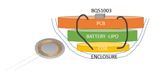
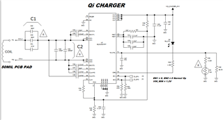
I am using the BQ51003 Qi WCP 1.2 compliant charger. Values on the schematic are not the ones being used now that was based on the EVM board for the BQ51003. The device is enclosed in a 1mm thick PLA 3D printed enclosure with a coil WR222230-26M8-G 27.20uH facing the plastic, ferrite touching a battery, and the PCB on top of it.
I followed the steps to calculate the C1, C2 matching capacitors to tune the coil.
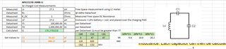
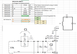
1. Measured the coil outside the enclosure free space = 27.20uH
2. placed the coil in the enclosure with all the components, battery and board. Measured 25.92uH
3. Used the equations provided by the datasheet, and computed C1 to be 97.72nF - used 100nF. C2 calculated as 940pF, used 820pF||120pF = 940pF
4. Soldered the components, 100nF rated at 16V (don't have 50V), others are 50V. Not sure if this is the issue or not
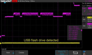
5. I place the device on the mat, and the mat starts blinking and blinking. I put the scope at the RECT output, and I see it going up and I see also modulation like. the LED connected at the output OUT blinks but won't go solid like when I put my cell phone on it.
6. Tried moving resistor ROS1(R37) to ROS2 (R36) 20K does not make a difference
7. Adjusted R34 392 ohms. Originally 110ohms as the EVM - Didn't make a difference.
So what other troubleshooting steps can I follow? Is the issue the coil not being tuned? The equations were followed to the letter - So why doesn't it lock? If you have a recommendation of scope shot I can add that too. I should also mention that after a while the LED stopped blinking and I could not get it do it anymore. Not sure if the battery got to a full charge state and there is no more load current being pulled from the charger. I will try with a discharged battery as well.
Any help will be greatly appreciated.
06/07/2021
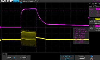
Added a resistive load to the OUT pin at the decoupling capacitors. The output ON TIME is 94ms every 2.5 seconds. it will not lock on always ON. The Status LED blinks as following the pulses but it will not stay ON. Any ideas what is happening? is it communications, tuning, or otherwise? Is there anyone that could help me resolve this?
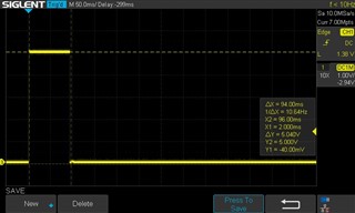
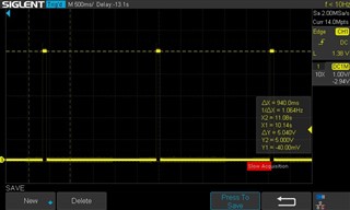
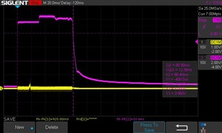
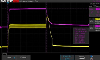
VRECT Magenta trace at the output decoupling caps of VRECT. the voltage swing is high.
6/7/2021 I can't reply to the threads for some reason.
-I have seen and read the posts you sent thank you.
- I don't know why it will not lock on. The charger pad LED keeps blinking, the Status LED on the BQ51003 OUT pin connected to CHG_N does blink as well, and eventually stops.
-I have removed the thermistor and shunted a 10K in the TS-CTRL pin, and it didn't make a difference nothing...
- I believe the coil is tuned per equations on the Datasheet. I am not entirely sure why it refuses to cooperate. I am using the correct coil 27uH.
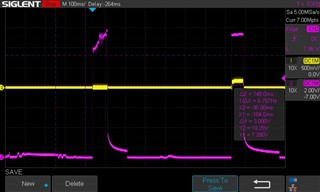
- VRECT tries to go high and then shuts off. I am not sure if too much power is reaching the Junction temp in the die and shuts off. The load is pulling 200mA from it @ 5V. It won't stay ON.

6/7/2021 1:20PM PST
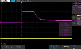
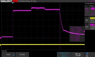
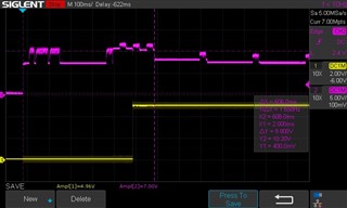
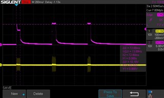
Instrumented better the VRECT capture . Voltage appears to reach 10.10V approximately See scope shot of VRECT. VRECT magnitude ~10V, 70msec duration, and repeats around 800msec...
Read a different datasheet from another vendor where they explicitly say to place the assembly (Receiver) on top of the TX coil and measure Ls' Equations looked similar to TI's so I tried that, but didn't work out either. The inductance shot up to 29.9uH. I should also note that I am measuring the inductance with an L/C meter but it doesn't put out 1Vrms as it is called out in the datasheet. I am not sure if this is the root cause. The L/C meter I am using is UCTRONICS L/C meter (https://www.amazon.com/UCTRONICS-Precision-Capacitor-Inductive-Capacitance/dp/B0856RCWBJ/ref=sr_1_1?dchild=1&keywords=UCTRONICS+High+Precision+Handheld+LC+Inductor+Capacitor+Tester%2C+Inductive+Capacitance+Meter+Kit%2C+1pF-100mF%2C+1uH-100H&qid=1623101912&sr=8-1). It does a decent job measuring accurately the Inductors I have presented to it. I have not measured the output voltage it puts out. Could this be the issue?