This thread has been locked.

If you have a related question, please click the "Ask a related question" button in the top right corner. The newly created question will be automatically linked to this question.

TPS53355: Loop instability of TPS53355

Part Number: TPS53355

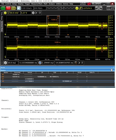
For tps53355, we test the dynamic response of the chip, and the voltage deviation is less than 5%. The test results are shown in the figure below. Please help to judge whether this power supply is abnormal?

The electronic load setting parameters are as follows:

Low value: 2A

High value: 15A

The rising slope is 2.5a/us

The descending slope is 5 A / us

Low position timing: 10ms

High position timing: 10ms

  • Hi ,

    Peter will help on this soon.

    BRs,

    Young

  •  

    76mV on a 5V output is +/- 1.5%, and I don't see any ringing or oscillations that would suggest instability or load phase margin so I don't see any issue.

    There does seem to be some DC shift in the output voltage from 2A to 15A.  While it appears small, this load dependence might be worth looking into.  This could be real, or a measurement error.

    To check to see if it is real, measure the VOUT with a DDM  without the oscilloscope and compare the output voltage at the 2A and 15A load current levels.  If that is the same, the DC shift in the voltage measurement it a measurement artifact, likely from the oscilloscope having passive ground probes connected to more than 1 ground point on the PCB, and the load current inducing a ground drop between those points.

    Output voltage is dropping between 2A and 15A, there are a couple of additional things we can look at:

    1) Is the converter operating in DCM mode at 2A?

    The TPS53355 converters D-cap mode control scheme is based on valley regulation, in DCM, the ripple voltage increases due to DCM operation, that causes the average output voltage to be slightly higher.

    2) Is the ground voltage shifting under load?

    The TPS53355 regulated the FB node with respect to the GND, if there is a voltage drop between the GND at the IC and the ground at the output due to the flowing ground current, 

    3) Increased noise on FB?

    Because D-CAP mode control is valley voltage regulated, if there is additional high-frequency noise on FB due to the increased load current, the D-CAP mode control can trigger on this high-frequency noise and cause the output voltage to rise with increased load current.