This thread has been locked.

If you have a related question, please click the "Ask a related question" button in the top right corner. The newly created question will be automatically linked to this question.

BQ25792: Device fails on powerup

Part Number: BQ25792

Hello!
I went ahead and built this previously reviewed schematic on a custom PCB.
To test it I powered it with a current limited 18v, with No battery connected initially. No load connected either, just standalone charger circuit (Im attaching the schematic again) - no MCU, no I2C host, nothing, just the BQ chip with this schematic. 
Initially the green LED D2 comes on for a few seconds, and then the input 18v source shuts down due to over current - then on the input net is permanently shorted. I also see that the PMID net is also shorted. Likely the chip is now dead. After removing the chip the short is no longer seen. The assembly is first tested for shorts, so it's something that is happening after powering the system.  

This happened on two attempts on two different PCBs built for the same schematic. 
Am I missing something here? Can you see anything done incorrectly that may lead to this failure?

- I have not connected the battery
- I have not connected any load
- I have a 10k on the thermistor point
- No I2C pull-ups, No I2C host
- INT_n is not connected to anywhere other than the pull-up

Any leads to trouble shoot this issue greatly appreciated please. 
Thanks,Bq25792_schm_ex.pdf
Srikanth

  • Hi Srikanth,

    I do not see any obvious errors on the schematic.  Do the boards function if you add a battery at BAT?  With no battery, the charger requires charge to be disabled by CE bit or pin or TS fault due to missing thermistor.  If not disabled, the charger converter periodically stops switching due to OVP fault.  This should not damage the IC.

    This IC is sensitive to layout.  Did you follow the diagram in the layout section of the datasheet and/or the EVM exactly?   Are the capacitors voltage ratings sized to account for ceramic capacitor derating due to applied voltage?

    Regards,

    Jeff   

  • Hi Jeff,
    Thank you very much for your quick response as usual.
    I understand that without battery (and TS) it should stop switching, but why does it get damaged?  
    Yes, have followed layout guidelines - although not exactly as EVM.  
    Capacitors are well overrated - all rated at 50v, and input was 18v. 
    Besides, after IC is damaged, I removed the IC and the short goes away - so caps are not the issue. 

    Attached is a screenshot of TOP and BOT layouts to give an idea. 
    Pads under the IC are solder masked covered.
    Any other thoughts? Meanwhile will re-assemble another and test with battery this time. Still, should not have got damaged. 
    Thanks,
    Sri
     TOPnBOT_layout.pdf

  • Hi Sri,

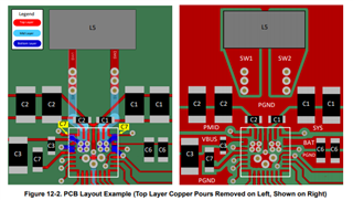
    The layout does not follow the recommended layout because the PMID and SYS ground return uses vias instead of connecting on top side as shown below:

    The only issues we observed when using a layout like yours was the IC being power limited but no destruction.  When you test again, please attach oscilloscope probes on VBUS, PMID. BAT and SYS test points and monitor first power up.

    Regards,

    Jeff  

  • Thank you for your response once again. 

    Tried again with a new device on the same PCB. This time there is no short, but the converter did not start.
    A 4S Battery was connected, and BAT and SYS voltages were present. Source of 18v did not seem to matter and there was no current through 18v source beyond 40 mA.
    A load of about 800mA was also present, and was entirely sourced from the battery through SYS.
     
    With this different behavior on the same board makes me think that there is an assembly issue on the board. 
    So first let me reassemble and get it xray inspected before I spend more of your time and attention.

    Thank you for your prompt attention!
    Will be back,

    Srikanth


  • I have assembled more boards and also got the assemblies Xray inspected for correct assembly of the BQ chip before repeated tests.
    But the trouble continues. Lost another device within a few seconds of connection (BAT pins are now shorted to ground). 
    (1) Will a 4S battery with built in BMS cause any issue?
    (2) Will absence of 2x10uF (as seen on data sheet pins table recommendation) on BAT pins (22,23) lead to this type of device failing? 
     Thanks for looking at this,
    Sri

  • I repeated test with a new board, new device - this time adding the 2x10uF on BAT line.
    Also replaced battery with a 4S battery without BMS.
    Same result - device failed upon power on. Presents shorts on BAT, VBUS.
    To begin with no short, SYS and BAT show battery voltage - before first power ON.
    Soon after 18v turned on to input, within 2 seconds both VBUS and BAT pins appear shorted and device fails. 
    Any insights please?
    Thanks!

  • Hi Srikanth,

    I still suspect a board assembly or test setup problem.  Can you replace your board with a BQ25792EVM and see if it is damaged?  Can you provide oscilloscope shots of VBUS, SYS and BAT at power up?

    Regards,
    Jeff

  • Not easy to lay my hands on a BQ25792EVM. But the device failing was seen even before any type of test attachments were attached. So it is unlikely it is a test setup issue. On the second batch of boards the device assembly was done by a high end assembly house and duly verified by Xray imaging - so unlikely it is assembly too.
    Rest of the components on board are rather trivial in assembly complexity, and I am quite confident of no such issues.
    I wonder if I got the schematic design wrong somewhere. 
    Oscilloscope shots are not available now. A video capture of the sequence of of events that also shows the scope screen is available, not sure how useful it may be.
    It is here: https://youtu.be/qw2m1Gil_Wk
    at 0:21 battery is connected to the PCB - BAT and SYS traces are seen to rise to Battery voltage
    at 0:48 18v input power is applied to VBUS. Immediately VBUS and PMID traces are seen to rise - but just for one second. LED D2 on REGN is seen to glow momentarily and at 0:49 all traces are low. Battery circuit opened due to high current (short circuit on BAT pin) and input 18v supply went to current limit at 2 amps. 

    Thanks,
    Srikanth 

  • Hi Srikanth,

    Are you able to communicate via I2C with the device at startup?  If so, can you provide register dump after you attach the BAT and then again after you attach input power?

    I suspect some sort of voltage spike at battery or adapter plug in but would need an oscilloscope shot to confirm.

    Regards,
    Jeff