This thread has been locked.

If you have a related question, please click the "Ask a related question" button in the top right corner. The newly created question will be automatically linked to this question.

TPS2HB16-Q1: TPS2HB16A does not give output on both channels despite being enabled

Part Number: TPS2HB16-Q1

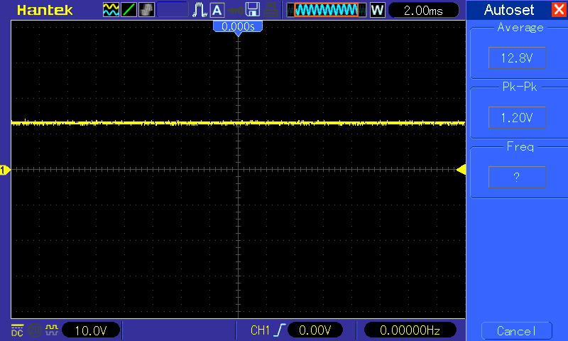
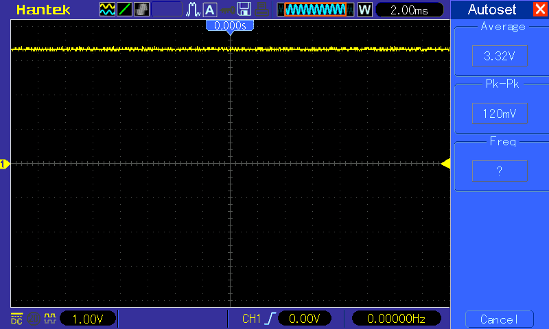
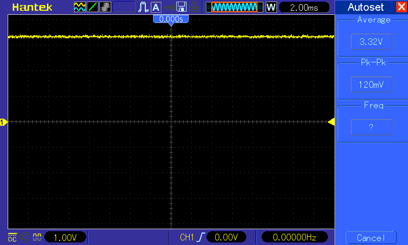
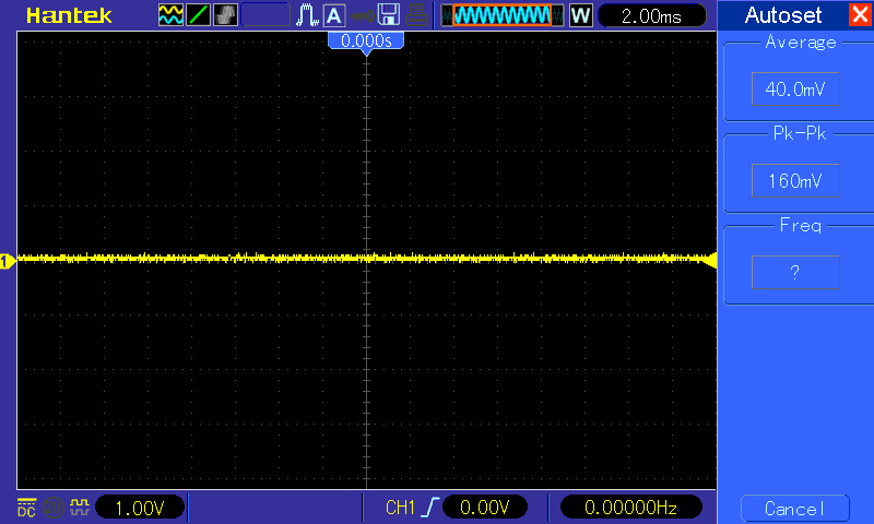
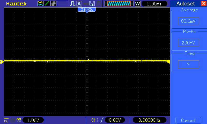
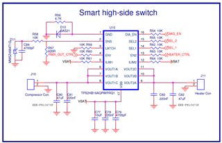
We are using TPS2HB16AQPWPRQ1 for a project. We are facing a problem. We are seeing 60-70% of failures in our devices. TPS2HB16A does not give output on both channels despite being enabled. Sharing the schematics used in our board. The enable signals are controlled by a controller with 3V3 logic high levels. We are following all the guidelines mentioned in the datasheet but we are still facing issue with the output. We checked soldering connectivity as well. There is no difference in the functional vs non-functional board except that the IC is not giving output. This is a showstopper for us. Hoping to find some solution as quickly as possible to resolve this. As part of debug, we checked the SNS pin voltage levels hoping to find some fault. Here are the observations we made: 


Logic Levels 

VSNS Voltage  

Output Voltage 

Device Type  

SEL1  

SEL2  

DIA_EN 

EN1 

EN2 

NON - Functional Board  

0  

1  

0V  

0V 

0  

0  

0V  

0V 

1  

0  

0V  

0V 

Functional Board 

0  

1  

0V  

11.1V 

0  

0  

0V  

11.1V 

1  

0  

0.57V 

11.1V 


  • These values are measured with respect to Digital Ground and with no load conditions 
  • Switch is powered by battery of 12.6V Li-ion battery with 11.1V current voltage level. 
  • GPIO logic high level voltage is 3.3V 


TPS2HB16AQPWPRQ1.pdf    

We are looking for some help to solve this issue. 


Thanks 

  • Hi Viraaj,

    Thanks for contacting us. Could I collect a few more pieces of information?

    1. For functioning board, both channel has 11.1V output, whereas the non-functioning board, both channel has 0V output correct?

    2. For the non-functioning board, could you collect waveform at VBB pin, EN1 pin, VOUT1 and VOUT2 pin?

    3. By no load, you mean put the load to open correct? It's a little puzzling to me that for the functioning board, it should detect the open load condition and pull the SNS pin high, but it stays at 0V. 

    Thanks and looking forward to more information from you.

    Regards,

    Yichi 

  • Hi Yichi,

    Thanks for the response. Please find the answers inline.

    1. For functioning board, both channel has 11.1V output, whereas the non-functioning board, both channel has 0V output correct?

    >> Yes that is correct.

    2. For the non-functioning board, could you collect waveform at VBB pin, EN1 pin, VOUT1 and VOUT2 pin?

    >> Attached waveforms. The voltages were
    VBB - 11.1V (w.r.t. digital ground), 10.57V (w.r.t. IC ground)

    EN1 - 3.26V (w.r.t digital ground), 2.63V (w.r.t. IC ground)

    VOUT1 - 0V (w.r.t digital ground)

    VOUT2 - 0V (w.r.t digital ground)


    3. By no load, you mean put the load to open correct? It's a little puzzling to me that for the functioning board, it should detect the open load condition and pull the SNS pin high, but it stays at 0V. 

    >> Yes, the load is open and EN1, EN2 pins are high. SNS shows 0V.

    Thanks

    Viraaj

  • Hi Viraaj,

    It looks like the device has no fault, and it's not enabled. Since there's a ground protection diode, that introduces ~0.7V voltage drop, which causes the control signal seen by the IC to be lower (verified by your measurement). Although it's still above the 2V threshold, and theoretically it should be turned on, could you try to give EN pin a 4-4.5V voltage with respect to the digital ground and see if the FET is able to turn on?

    Regards,

    Yichi

  • Hi Yichi,

    We checked with 5V on EN pins, it still gave no output. We also did another experiment where we replaced the IC on a non-functional board with an IC from a working board, it works on the non-functional board now. Do you think ICs are damaged? If so, is there anything which comes to your mind on how they can be?

    Thanks

    Viraaj

  • Hi Viraaj,

    It could be something to do with the manufacturing and solder reflow. Could you try to put the IC that's not working on the EVM or other good board to see if it will function?

    Regards,

    Yichi