This thread has been locked.

If you have a related question, please click the "Ask a related question" button in the top right corner. The newly created question will be automatically linked to this question.

BQ24616: Charging current is far lower than it should be.

Part Number: BQ24616

Hello everyone

I have recently designed a charge controlled for a 3-cell Lithium-Ion battery using the BQ24616. Apon testing the board, I noticed that the current that the battery charges at is much lower than it was designed. The charge controlled was designed to for a fast charge current of 4.5A but I am only getting 1.35 A. Below are the full design parameters:

Vin = 24 V

Vbat  = 12.6 V

Iadp = 3 A

Iprechg = 0.45 A

Ichg = 4.5 A

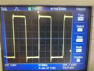
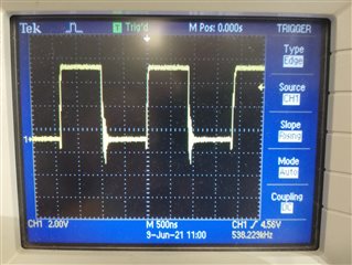
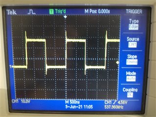
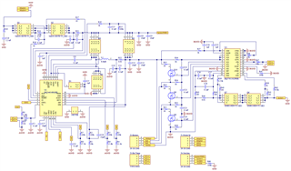
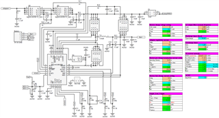
And here is my schematic as well as screenshots of the design calculations, from the tool provided by TI:

The test was conducted using a laboratory power supply, set at 24V and 6 A, as the power source. All the FETs that control the power switchover are working and the battery does start to charge when the power supply input is applied. the charge current is just too low.

I tested two different batteries, one from low state of charge and from from a medium state of charge, with the same results. I charged both batteries with the lower charge current of 1.35 A until the charger stopped charging. This stop occurred at 12.45 V, rather than 12.6 V as per the design. The controller is supposed to end with a constant voltage phase and then terminate with a low current (0.45 A as per design), yet I did not observe a constant voltage phase and charging was terminated with 1.35A still flowing.

Here are the snapshot values of all the parameters that I could measure during charging:

Supply current: 0.7 A

Supply voltage: 24 V

Charge current: 1.35 A (design value: 4.5 A)

Charge voltage: 11.1 V

Fb pin voltage: 1.893 V (measured over R1) 

Iset1 pin voltage: 0.95 V (measured over R8) (design value 0.9 V)

Iset2 pin voltage: 0.631 V (measured over R6) (design value 0.45V)

ACset pin voltage: 0.660 V (measured over R4) (design value 0.6 V)

TS pin voltage pin: 2.11 V (thus within temperature range)

REGN pin voltage: 5.938 V

Vref pin voltage: 3.271 V

There was one other thing I noticed while taking the measurements that could be relevant: When I was measuring the Iset1 voltage over R8 (the one responsible for programming the current limitation), the charge current jumped to 2.15 A. As I stopped measuring (removed the probe) the charging current went to 0 A for a second and then resumed at 1.35 A like normal.

I would greatly appreciate it if anyone can help me to understand this strange behaviour or point out a possible mistake in my design. Thanks in advance.

  • Hi,

      It looks possible that the ground routing for your board is not ideal. This is why it is sensitive to your multimeter, as well as the shift in expected ISET1, ISET2 versus measured values. Can you take a waveform of SRN, PH, HIDRV and LODRV when the part is switching in CC mode? Do you have any other circutry hanging between the battery and SRN? Also are you using your real battery for the output when testing your board?

  • Hi Kedar, thanks for your reply.

    Below are the waveforms you requested. If I understand you correctly, there is no other circuitry between the battery and SRN. There is however also a battery protection and cell balancing circuit. This circuitry can disconnect the negative of the pattery from the ground with some FETS. I have also included a schematic that also shows this part bellow. If you are convinced it is a problem with the ground, could you please offer some guidelines for possible fixes?

    HIDRV:

    LODRV:

    PH:

    SRN:

    Updated Schematic with battery protection part:

  • Hi,

       Can you try testing using an eload to simulate your battery? If you can attach a bulk cap at the output and program eload into CV at the same voltage as your battery that will be helpful. In these tests we want to disconnect the part of the circuitry that has the battery protection, and isolate the charger IC performance.

  • Unfortunately it is not possible for me to disconnect the battery protection circuitry. I also don't have bulk caps on hand. I also don't believe that will work anyway, since the IC will not start to charge is the battery voltage is below a certain level (its part of the built in functionality). so I don't believe it will start to charge a cap at 0V anyway.

    Do you have any other theories or things that I can try?

  • Hi Johannes,

       The eload would fix the voltage on the bulk cap while being able to sink current (charging a battery), and the bulk cap simulates the large surface capacitance of a real battery. Since that is not a feasible option, are you able to test your conditions on an evaluation module? I am hoping to isolate the IC performance from the rest of the system. The conditions you have should work fine on the evaluation module.

    What is the part number/datasheet of the inductor you are using?

    Also can you share a picture of how your AGND and PGND are connected?